Continue to Site

Eng-Tips is the largest engineering community on the Internet

Intelligent Work Forums for Engineering Professionals

  • Congratulations waross on being selected by the Eng-Tips community for having the most helpful posts in the forums last week. Way to Go!

ABAQUS :Problem with analytical field definition and implementation in Boundary Condition

Status
Not open for further replies.

VaggelisKas

Industrial
May 11, 2015
36
Hello community,

I have the following problem:

I am trying to simulate a cutting process in which the tool needs to follow a specific
route along the part.
The route is defined by a specific mathematical sentence.
I define the sentence in the analytical field toolset and I define a displacement boundary condition
in the first step.
However, when the job is finished my tool is highly deformed.
There is nothing wrong with the material specifications because the same materials have worked
for a plethora of other cutting simulations.
The documentation is a little blunt as regards the analysis of the Field toolset and I would appreciate any help possible.


Best regards.
 
Replies continue below

Recommended for you

Hi,

Is the path followed by the cutting tool correct? If not there must be an issue with your equation or it has not been implemented correctly. Hard to say more without more detail?

Dave
 
Hello and thanks for your answer.

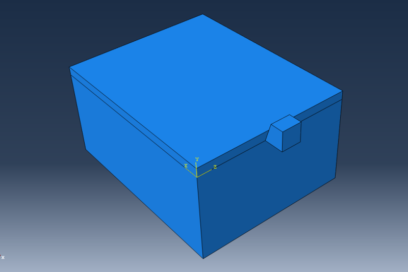
Below one can see my assembly:

Untitled_j6fqln.png


I need my tool to follow a curve along the part.

The curve is defined by the sequence:

X=SQRT((Z^2)-20^2), using the correspondent datum axis as used in the assembly.

My boundary condition regarding the displacement value is seen below:

Untitled1_m3sy65.png


Meaning that by the end of the job, the tool needs to be at point (X,Z)=(20,0)

I can not seem to find a correct way to implement this curve in an analytical field expression.

Any tries attempted resulted in an extreme deformation of the tool.


Any kind of help would be highly appreciated.

Best regards to all.
 
Hi,

I would set up a simple static analysis with just the tool to the boundary condition. The analysis should run very quickly and you should be able to see whether or not the tool is following the desired path. If the tool does not follow the desired path, you know you have a problem with your equation or how it is implemented. And you should be able to debug the problem very quickly in Standard. Once you have confirmed that the tool is following the desired path, go back to explicit, update your boundary condition and rerun your original analysis. If you get the same error, at least you know its not caused by your expression.

Its hard to tell from your post what is causing your issues. You specified an amplitude which could be causing problems? and you have not given the actual expression that you specified in CAE. Also, the equation you gave describes a position while your boundary condition applies a displacement. Could there be some mixup here?

Good luck,
Dave
 
Hello and thank you very much for your answer.

I know that the problem lies with the implementation of the equation in the analytical field, because I run the simulation with no problems for a uniformly applied displacement within the boundary condition.

I also run the static analysis in Standard that you advised, and the mistake lies with the mathematical expression because the tool does not follow the path I need.

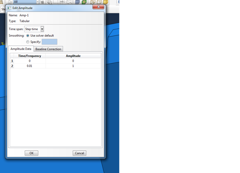
The amplitude I use for the displacement boundary condition is a simple tabular Amp as seen below:
Untitled2_urlcqu.png

The overall step time is 0.01 sec as is the span of the amp.

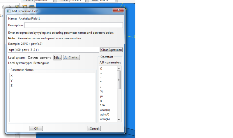
The expression I used is :
Untitled4_p4hgzm.png

which is a mistake.

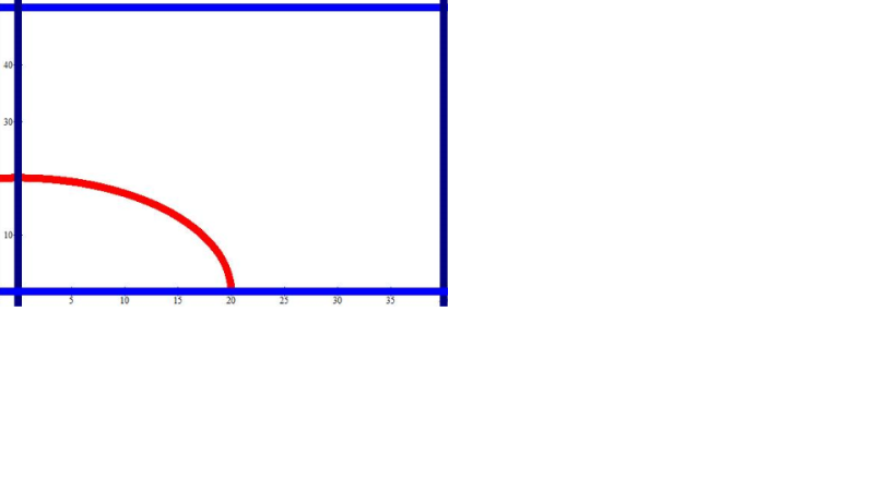
What I want to achieve is shown below:
Untitled3_ov8b3r.png

Imagine that the red curve is the path I need my tool to follow along the part.
The red curve is the function X=SQRT(400-Z^2) with the axis used as in the assembly.

Once again, thank you for your help and any kind of more comment would be highly appreciated.


Best regards.
 
In addition I tried to constraint the tool as a rigid body and I applied the boundary condition to the reference point.

But no matter what analytical field I implement I get the message that all displacement equals to zero due to that analytical field.

Any ideas would be highly appreciated.
 
Take your formula, go to Excel and create two tables
x vs time
z vs time

Use these data as two amplitudes.
Create two boundary conditions (x only, z only) and apply one amplitude per BC.
 
Worked like a charm!!!

Thank you very much Mustaine3!


Best regards.
 
Status
Not open for further replies.

Part and Inventory Search

Sponsor