Continue to Site

Eng-Tips is the largest engineering community on the Internet

Intelligent Work Forums for Engineering Professionals

  • Congratulations IDS on being selected by the Eng-Tips community for having the most helpful posts in the forums last week. Way to Go!

AC Drive tripping motor protection switch heat problem 3

Status
Not open for further replies.

martinrelayer

Electrical
Oct 26, 2007
68
Hello!

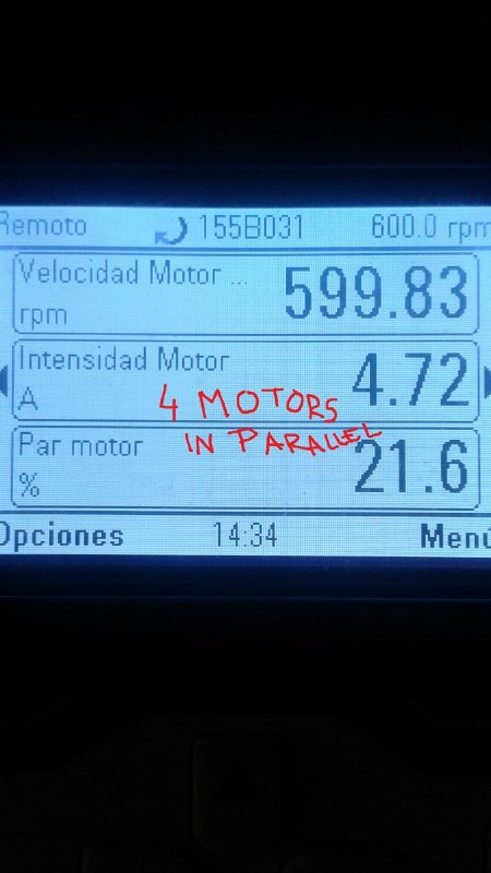
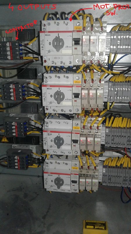
we have here one AC drive (ABB ACS800) that has four (4) motor in parallel. The drive is 16amps and the motors are 0,75kw 1amp 690V each.
each output from the drive to the motor has an individual motor protection switch, sized to 1,6Amps
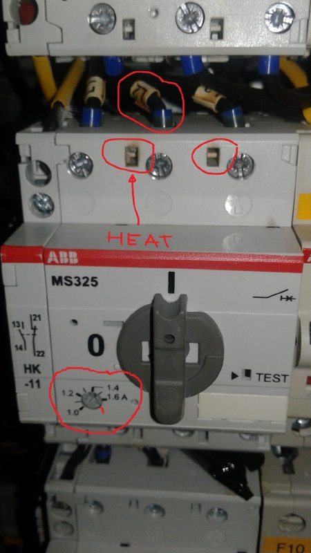
the thing is that te motor protection switch are heating too much today I measure voltage drop and I have 1 volt drop and 1 amp current in each phase.
please see attached pictures.

does anyone have any hint?? is that drive output to four motor in parallel has too much high freq component that causes overheat and problems with bimetallic mechanism??
the cables are 2mm and they are not overheated, also it has a contactor and not overheated, only the motor protection switch!!! I measure ac current rms and I measure 1 amp in each phase for all motors (all motors are the same)

any hint???
 
 http://files.engineering.com/getfile.aspx?folder=dc586142-450b-4672-a716-37dc8401956e&file=Pictures.zip
Replies continue below

Recommended for you

martinrelayer; Please just directly post the images
ice_screenshot_20160718-141231_hl2efs.png
into the thread so dozens of others don't have to go thru click-hell to see them.


20170508_151345_ze6wtx.jpg


20170508_151326_ltsdrk.jpg


20170508_151359_krvjeq.jpg


Yes you could be having heating from the carrier frequency. Have you tried turning down the carrier frequency to see if it alleviates the issue?

I doubt your meter is also giving you the correct info due to the same modulation frequency. A total of 3 measly watts spread over three contacts seems too low to be baking things as your pictures show. It may well be more losses than you're measuring.

Keith Cress
kcress -
 
The bootlace ferrules show signs of severe overheating: the blue sleeve has turned brown due to heat. This may well be the source of the heat which is affecting the thermal relay.

I suggest re-terminating the cables using a good-quality crimp lug with a flat blade or forked end, such as those made by Cembre or Elpress, and which are typically coloured blue for 2.5mm² cable. For example,
 
A) 99.9% of motor protection switches like that are not designed to operate at anything other than 50/60Hz. The bi-metal heating elements are not calibrated for variable frequency use.
B) Without even looking for and reading the manual for them, I'm going to go out on a limb and say that the installer (don't know if it is you or if you inherited this) did not follow the manufacturer's instructions regarding spacing and "heat stacking"; the problem of heat from one unit rising into the next, then the next, etc.. Most devices like that require at least 1" (25mm) of spacing, and even then if it is being used on a VFD circuit, I would not push the envelope, give any current carrying components plenty of room to "breathe". So so many times I see people try to cram way too much electrical equipment into spaces not suited for them, then complain about parts over heating.

Electricity flow = heat...


"You measure the size of the accomplishment by the obstacles you had to overcome to reach your goals" -- Booker T. Washington
 
I'm with Scotty. Check the lugs and check that the screws are tight enough. If there is serious heat damage from poor connection the devices may not be repairable.
If heat stacking is an issue the upper devices may be more prone to tripping.

Bill
--------------------
"Why not the best?"
Jimmy Carter
 
Thank you very much for your answers.

this MCC came as shown from factory but even though distance is short there must be something else.

I measured with an AC clamp true rms, 0,9-1,1 amps and I regard this as very low current to overheat the motor protection switches. The heat is true, you can't hold your finger on it. Someone changed one to 4amps and the heat is less, but still some.

the drive has no output filter, this I regard as a problem. Can the heating element inside the mot. prot. switch be affected by other frequencies than 50/60hz that I cannot measure with a true rms clamp?

best regards,
martin.
 
Last time I helped someone with an issue like this, the overload heaters were a coil around the bi-metallic strip. The overloads were getting very hot inside like you are reporting. I guessed that the bi-metallic strip was likely one part steel and the coil around it made it work like a very poor inductor core causing a lot of heating in the strip. Try an RMS electronic overload which uses CT's to measure the current instead of a bi-metallic overload.

 
Interesting find Martin. A filter on the drive output might be the next logical move, and on a small drive probably not too expensive - provided you have space to fit one.
 
LionelHutz good advice!!!

This I don't regard as big problem BUT they want to put 5 (five!!!) 15kW motors in parallel... so I was around this issue mainly because they want to do the same application but larger power in a couple of months!!
I didn't know of this problem but electricians have been changing motor protection switches for a while...

While looking at this and thinking on the same problem in larger power application... BIGGER PROBLEMS?!?!?!

Im thinking in advice for SINE output filter and electronic current measurement (using CT's)

Also DCS logic to power ON/OFF motors they are making WITHOUT stopping the drive!! Now operators can stop one motor without stopping all four. They reported once replaced the drive because of a fault but I think control logic must stop drive then exclude motor and start again!!

kind regards,
martin
 
I wonder if measuring thermal protection CT's must be iron core or hall effect. mainly thinking on this higher power application.

regs,
martin.
 
My guess would be that larger would have less issues. The heaters would be heavier and shorter and likely not a coil making them less likely to be heated so badly.

You might be able to get away with stopping a drive while the VFD is running, but starting a motor on a running VFD is a bad thing to attempt.
 
Search for this pdf from ABB

I would review rules in this PDF that the manufacturer put out and see if that is the case.

Above the advice was to look at the freq that is put out by the drive. There is a particular rule that ABB put out that should be followed.

Para 2606 Effective switching freq = 4khz minimum
Other freq to start of 2khz should not be used.

Volts/hz setting was also stated as one of rules to follow.

Question: Does the drive disable when one of the motor protectors are tripped? I would think you would want to disable the drive if one of the motor protectors tripped.
 
yes motor prot switch should disable drive, you're right.
thanks to all

kind regads,
martin
 
Well that one link is from the VFD group, but makes no recommendations as to how to actually accomplish the overload protection. In this document from the Manual Motor Starter group within ABB, they basically say not to do it, but if you have to, take a number of precautions (page 39).


The right hand doesn't talk to the left hand I guess...


"You measure the size of the accomplishment by the obstacles you had to overcome to reach your goals" -- Booker T. Washington
 
This is AB recommendations, somewhat similar to both pdfs.
Quote-----------------
Challenges with use of standard MPCB at output of VFD
Reflections of the voltage pulses
Occur at the terminals of the motor due to the PWM voltage pulses and the surge impedance of the motor. Amplitude is dependent on:
System voltage
Voltage rise time trise of the VFD
Current rating of the MPCB (surge impedance)
Operational voltage (DCBUS-voltage)
Location of the MPCB (close to the VFD output or close to the motor)
Cable type and length between MPCB and motor (surge impedance)
MPCB rated < 10 A are more susceptible to voltage wave reflections (higher surge impedance)
Reflected voltage pulses cause high dielectric stress on the MPCB magnetic trip coils resulting in accelerated aging
Unquote----------------
then talk to a particular part number below
Quote----------------- I do not think both ABB ever talked to a particular part number?
AB 140M-D8V are suitable for application at output of VFDs in multi-motor installation
[highlight #FCE94F]PWM frequency ≤ 4kHz[/highlight]
VFD output frequency ≤ 400Hz
Current setting = rated motor current
Maximum cable length of drive instruction manual apply
Preferred location of MPCB installations is as close to the motor as possible
Unquote----------------
The ABB pdf is showing <8khz PWM freq
 
Howdy Martin,
If they wish to replicate this system with 15kW motors, and be able to start-stop with the contactors (ie not with the drive), what size of drive are you considering?
Currently the drive is 16amps and the motors are 0,75kw 1amp 690V each, and you are having issues. To extrapolate up to 15kW motors, you would require a 320A drive. Of course you won't go to this extreme (mostly because of cost). Obviously in this extreme example four (4) 20A drives would likely cost less then (1) 320A drive.
I would think that you would not wish to be less than 160A. This could accomodate inrush current (ie 7X IFL) + 3 remaining motors running at full-load.

GG

ps What is the nature of the load (ie constant or variable torque), speed range.

"I have not failed. I've just found 10,000 ways that won't work." Thomas Alva Edison (1847-1931)

 
Status
Not open for further replies.

Part and Inventory Search

Sponsor