Hi All,
I'm in the process of designing my own 3D lidar scanner (mostly for fun), but since I'm not a mechanical engineer I would love to get your input on bearing requirements.
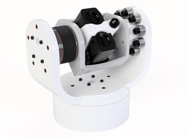
The lidar scanner platform basically consists of two motors each being able to turn the lidar in 1 axis. The platform will probably be used later on to mount different and potentially somewhat heavier units (up to 500 grams) than the currently installed lidar unit.
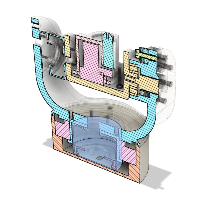
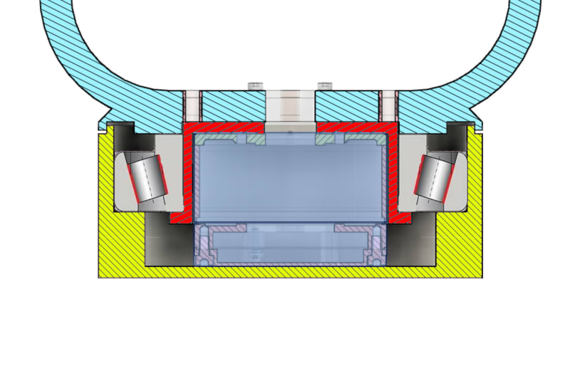
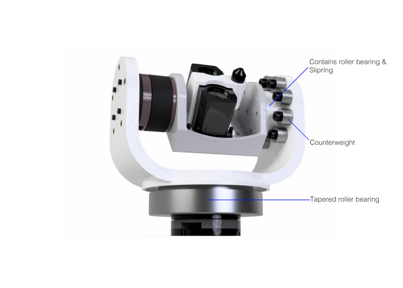
The current design looks like this:
I'm relying on two gyems motors, that both have their own microcontroller and 16-bit magnetic encoder. In my tests these motors provide excellent precision positioning, but data on the internal bearings is limited.
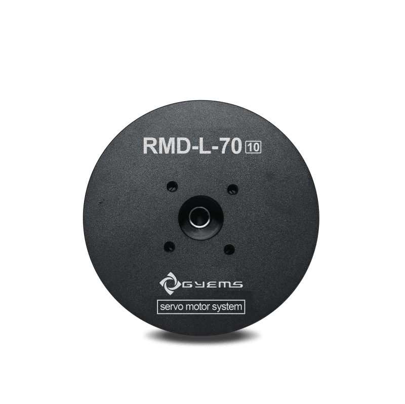
This makes my somewhat worried about the bottom motor, which is listed here: [URL unfurl="true"]http://www.gyems.cn/794879.html
[/url]
This motor would have to carry the weight of most of the scanner, and although it is plenty powerful I wondered what the impact on the lifespan of the bearings would be. The only information I can find on their website is that they use two roller bearings.
I was thus playing around with the idea of adding a bearing of my own in the form of a tapered roller bearing to take up both the axial and radial forces. Besides this potentially being overkill, the other problem with this solution is that the bearing would rest on the bottom (stationary) part of the scanner. Thus, if you would lift the scanner by the top part the weight of the bearing would essentially hang onto the bottom part of the motor (as the motor is the only thing holding both parts together). Since the tapered roller bearing adds a fair amount of weight might this do more harm than good?
Are there different bearing solutions that could also tie the rotating portion and the stationary base together, or is it just not needed?
I'm in the process of designing my own 3D lidar scanner (mostly for fun), but since I'm not a mechanical engineer I would love to get your input on bearing requirements.
The lidar scanner platform basically consists of two motors each being able to turn the lidar in 1 axis. The platform will probably be used later on to mount different and potentially somewhat heavier units (up to 500 grams) than the currently installed lidar unit.
The current design looks like this:
I'm relying on two gyems motors, that both have their own microcontroller and 16-bit magnetic encoder. In my tests these motors provide excellent precision positioning, but data on the internal bearings is limited.
This makes my somewhat worried about the bottom motor, which is listed here: [URL unfurl="true"]http://www.gyems.cn/794879.html
[/url]
This motor would have to carry the weight of most of the scanner, and although it is plenty powerful I wondered what the impact on the lifespan of the bearings would be. The only information I can find on their website is that they use two roller bearings.
I was thus playing around with the idea of adding a bearing of my own in the form of a tapered roller bearing to take up both the axial and radial forces. Besides this potentially being overkill, the other problem with this solution is that the bearing would rest on the bottom (stationary) part of the scanner. Thus, if you would lift the scanner by the top part the weight of the bearing would essentially hang onto the bottom part of the motor (as the motor is the only thing holding both parts together). Since the tapered roller bearing adds a fair amount of weight might this do more harm than good?
Are there different bearing solutions that could also tie the rotating portion and the stationary base together, or is it just not needed?