Eng-Tips is the largest engineering community on the Internet

Intelligent Work Forums for Engineering Professionals

  • Congratulations waross on being selected by the Tek-Tips community for having the most helpful posts in the forums last week. Way to Go!

Adiabatic compression in oxygen systems - pointers to literature

Status
Not open for further replies.

Prometheus21

Mechanical
Apr 22, 2023
103
0
0
NO
Hi all,

Approaches to compressible flow varies, but applications are often assumed to be either isothermal or adiabatic. For longer pipelines isothermal flow conditions are usually adequate, and the Crane technical paper 410 is a well used resource. It does however lack when describing adiabatic flow, and I'm looking for additional literature on this area.

Problem background:
My company (small - located in Europe) manufactures a multitude of gas fittings, valves, filling equipment and the like. Everything is cleaned for oxygen service iaw. Praxair GS-38 (now obsolete).

A typical adiabatic flow application of interest is high pressure hoses. Fluoroplastic tubing, ID:6mm, burst pressure 1200 bar, Wp: 300 bar. Total length: typically 1-3m length. Typical gas to be filled/used: oxygen. Due to the extremely volatile nature of high pressure oxygen, strict regulations exist regarding testing, approvals, precision cleaning ect.

The maximum flow capacity is thoroughly documented during the extensive testing. This applies to every type of equipment produced. I'm however more interested in learning more about actually modeling and calculating the flow of fluid through valves, fittings, pipes, hoses ect. given a high pressure differential, rapid filling times and well insulated systems; adiabatic flow.

My question is this: can you guys recommend any good literature on this topic? The amount of heat generated by friction is minute, but being able to model both with and without friction would be helpful.

Thank you for any input you may have!

 
Replies continue below

Recommended for you

Graphs for adiabatic flow behaviour in pipes is presented in Perry Chem Engg Handbook - see page 6-23 onwards in the 7th edn. A numerical procedure is also described in this section. These graphs are also to be found in the API on pressure relief systems design. The mathcad routine I built for this based on this numerical procedure many years ago doesnt seem to produce reasonable results on pipe exit temp - hope you have better luck.
 
Thank you! I will look into it.

My apologies for the confusion, I should have been a lot more clear in my title description.

During longer "usage" times the flow can be assumed isothermal. This is not always true however, when the rapid compression takes place, and you get strange effects when moving from 200 to 300 bar pressure.

Lets say you have a gas cylinder with 99,5% oxygen purity, at 300 bar pressure. When the valve is opened quickly the oxygen will rush into the stem of the attached pressure regulator, and then into the high pressure hose (often the pressure regulator allows for an outlet pressure of 300 bar as well - non regulating at that point), adiabatic compression is now a very real danger in both the regulator and the hose when the gas reaches the end of it.

Now here is the interesting part: When shock-testing a hose for adiabatic compression (ignition test), the hose is quickly filled and evacuated for many cycles. At 200 bar the hose can instantly rupture when the gas reaches the end of the hose, your typical "gas hammer effect/metal fire". At 300 bar this still holds true, but you can also get a delayed adiabatic compression effect where the hose ruptures at multiple sections: the outlet (typical), the inlet(!) and somewhere along the length of the hose. We have yet to see this happen at 200 bar. This also tends to happen more in hoses lined with PTFE compared to PFA, which is strange since PTFE is slightly more resistant to heat.

This can happen as along as 60-90s after the initial valve opening, completely changing the testing requirements for this pressure range and product group.

So firstly I need to refresh my knowledge on adiabatic compression - hence the request for literature, and then see if I can model the adiabatic flow when the valve is initially opened.

Again, thank you for the input!

 
Snickster: Thank you, I'll check it out! I regret selling my old college textbook now..
I remember my old colleague using Gas Dynamics (I & II) by Zucrow and Hoffman extensively before he retired; a shame I didn't get my hands on some copies back in the day.

So during ignition testing the hose is dead ended in one end. The other end is connected to a dual contraption that allows both filling and evacuation of the hose, respectively. This allows rapid pressurization/depressurization.

The inlet part of the contraption is connected to multiple cylinders in a racket "booster" formation, allowing continuous shock-testing for many cycles, at constant inlet pressure; of course some variations do exist. Some hoses only get shock tested (common), and some get a follow-up testing where the hose is repeatedly pressurized for 3 minutes, trying to provoke a delayed rupture described earlier (less common when ignition testing).

Of course both alternatives you mention is used extensively in the industry: open to atmosphere, and connected to a some form of vessel. And while rupturing of a hose due to adiabatic compression/decompression is rare, we have had customers experience it in both applications. Now understandably a delayed metal fire when opening a cylinder valve is extremely scary - which is why a lot of the customers in general want some form of heat sink connected to the hose. But that is another discussion entirely.
 
So I will try to explain my understanding of physically what is happening regardless of whether the end of the hose is open or connected to a vessel.

When you open the cylinder shut off valve flow begins first through the valve and then through the regulator and then the hose. First look at case if valve did not have anything connected to it downstream such as regulator and hose. In this case the valve is basically like a converging-diverging nozzle but with friction. In an ideal converging nozzle the maximum velocity possible is the speed of sound where Mach = 1. The proof of this is using differential form of the continuity equation PAV=C and substituting other relationships (this is derived in the above reference book). It is found that with an adiabatic isentropic expansion in a nozzle the maximum velocity at the throat is mach 1 and to increase the velocity further converging nozzle will need to be followed by a diverging nozzle to develop a speed higher than mach 1 (this is also derived in the above reference book).

So the in the valve the flow increases to mach 1 at the reduced port hole in the middle of the valve. To get to the velocity of mach 1 the kinetic energy of the velocity comes from the enthalpy of the fluid itself as the fluid undergoes an almost isentropic adiabatic expansion but with some friction. Ignore the friction for now. So in an isentropic expansion the upstream pressure versus downstream pressure, and upstream temperature versus downstream temperature, is related by the isentropic adiabatic P/T relationships. So as the velocity increases to mach 1 in the port hole of the valve, the pressure drops and the temperature drops in accordance with the P/T equations of isentropic adiabatic flow.

Now if the maximum flow in the smallest diameter point in the valve is limited to mach 1 then so is the pressure and temperature at that point. In other words the flow is choked at mach 1, corresponding to a fixed pressure and temperature at the throat – critical choked flow conditions, that is greater than the downstream pressure. For Oxygen the pressure at the throat is 0.528 times the upstream stagnation pressure (this can be found by finding resulting pressure after isentropic adiabatic expansion to sonic velocity) and the temperature is 2/k+1 times upstream stagnation temperature (the isentropic temperature at choked pressure). The velocity cannot increase above sonic at the throat so only thing that can be done to increase flow is increase upstream pressure, still velocity at throat will be sonic but just at a higher critical throat pressure and temperature, but flow will be greater. Downstream of the valve the flow will discharge into the atmosphere where downstream side of the valve is an extremely imperfect diverging nozzle. The pressure at the throat of the nozzle will dissipate to atmospheric pressure via irreversible shock waves and loss of this energy with some increase I imaging in jet velocity exiting the valve port. If the outlet of the valve was an ideal divergent nozzle then the flow will increase to above sonic by using up the energy still contained in the fluid at the pressure and temperature at the nozzle throat.

So now add the regulator to the piping system. The regulator then acts just like the shut off valve. Since the regulator keeps backpressure on the shutoff valve then the shutoff valve just experiences normal subsonic flow with friction loss. The regulator is now where the sonic flow occurs as described above. At the orifice of the regulator the flow is sonic mach 1 and pressure and temperature can be found by isentropic adiabatic equations.

So now you attach a hose to the regulator and what happens? The regulator will still flow sonic at the orifice since the downstream pressure is low enough that the fluid has enough energy to reach the limiting sonic velocity at the orifice port. The flow in the hose may want to reach sonic if the pressure is low enough and the tube is small enough diameter such that the flow will need to reach sonic in the hose base on the flow coming out of the orifice of the regulator. However due to flow equations the following relations existing for flow with friction: If velocity is below mach 1 then in a constant area tube with friction, velocity will increase with decrease in pressure; if velocity is greater than mach 1 then for a pressure drop due to friction the velocity would decrease in a constant area tube. Therefore the velocity neither increases or decreases in the pipe but any sonic flow developed in the pipe will travel down to the end so that sonic velocity in any pipe can only exist at the end of that pipe, and greater than sonic velocity cannot exist inside the pipe length.

So in the case of your hose you are developing sonic velocity, sonic pressure and sonic temperature at the end of the hose. The pressure would be 0.528 times the upstream 200 or 300 bar pressure but with friction in the upstream valves and hose the pressure is somewhat lower (the above reference book shows how to calculate using Fanno Flow Equations with friction). So at the tip of the hose you have sonic velocity, pressure equal to 0.528 times 200 or 300 bar, and temperature of 2/k+1 times stagnation temperature in cylinder (where k is ratio of specific heats). Add friction loss to this as you travel back upstream to get the actual pressure inside each section of the hose. So you can see that at lower 200 bar cylinder that the hose only burst at the end, but at 300 bar the hose burst all over because it can’t take that higher pressure which is pressent throughout the hose with friction added as you go upstream. The main point that you need to understand is that flow cannot reach above sonic in a pipe of constant diameter and if it does reach sonic it will always be at the end. And that there is a discontinuity of pressure at the end of the pipe where sonic flow occurs. Just inside of the pipe may be 150 bars but just outside is atmospheric and there is a tremendous loss of this energy through irreversible shock waves across the end of the pipe. Also with friction pressure increases from the sonic flow pressure at the end of the pipe as you travel back upstream, Note that if the hose were long enough (say 1000 feet for example) the pressure upstream could increase so much by adding the friction drop such that the regulator sees so much backpressure it loses capacity and flow is reduced.
 
From your description of this ignition test, where the end of the hose is closed, it sounds like hose rupture occurs by either or both of these effects:
a) Gas hammer, similar to water hammer, due to high momentum change, which results in localised transient hammer pressure exceeding supply pressure
b) The attendant compression effect from each hammer event, repeated over several fill cycles in quick succession, causes heat buildup ( adiabatic compression effect) which brings the thermoplastic liner (or some other exposed metallic component in the hose) up to ignition temp is this pure O2 atmosphere.
Is this what happens?


Snickster: Thanks for the input. I can tell I have to refresh my knowledge of gas dynamics, but what you describe makes sense from a practical standpoint.
"The flow in the hose may want to reach sonic if the pressure is low enough and the tube is small enough diameter such that the flow will need to reach sonic in the hose base on the flow coming out of the orifice of the regulator." - That would make sense. In my experience it is the 6mm (ID) hoses that can rupture at multiple spots at these pressures; I have yet to see that happen to a 10 mm (ID) hose. What usually happens here is the typical gas hammer effect - rupture at the end.

georgeverghese: Correct. The heat of compression (gas hammer, rapid pressurization, adiabatic compression) is the most efficient igniter of nonmetals, and while a fluoroplastic tubing is quite resistant to ignition, it does happen from time to time. The big x in this equation is the level of cleanliness, any particulates striking the tubing (particle impact) will create additional heat buildup. That in combination with the oxygen lowering the flammability limit of the materials, you can get easily get a fire going. And we haven't even began adding flow friction and resonance in the equation (where resonance usually is more of a problem in metal tubing - especially with higher harmonic frequencies as these have been shown to produce higher system temperatures). Determining the cause of a hose rupture can therefore be difficult at times. That being said most of the accidents tends to happen from improper rutines when it comes to cleanliness at the customer site when connecting/disconnecting the hoses during operations. The worst case I ever saw was seeing someone replace an existing hose with a new one. The new one was laying unprotected on the floor, uncapped, allowing dirt and particulates to recontaminate the hose.

When ignition testing the hose for third party approval the following specs are usually required by the customer:

Test gas supply: industrial oxygen (min 99,5%). (For medical equipment other specs are required)
Gas temperature: approx. 60℃.
Test pressure: 360 bar. Multiple cylinders are connected to the inlet valve using a distribution network, ensuring constant test pressure at all times ("booster")
Number of cycles: minimum 20, 50 is often required.
Connection tube length 1m
Connection tube internal diameter: 6 mm.

The hose is connected to the connection tube, and dead-ended.
I do not have a diagram of the external party setup ready at hand, I'll se what I can come up with as we are prepping for a new round of third party testing and approvals in the near future.

For everyday manufacturing the following applies: each hose is tested hydrostatically with clean water at 2x max WP followed by shock testing 3-5 cycles with oil-free air at 1-1.5 x WP, and finally a leakage test lasting for approx 3 minutes at 1x WP. The customer requirements tends to change, and the shock-testing part seems to be phased out within a year or two per regulations.

That being said I appreciate your inputs. My interest in this is mostly academic; testing and verifying the design is one thing; understanding why certain things tends to happen is another. But at least now I have a starting point as to where to begin with the modeling of adiabatic compression and initial flow behaviour.

 
As you say, in many cases, hose rupture / ignition may also be caused by residual dirt particles in the hose in this high purity O2 atmosphere with much lower autoignition temp. Would suspect that, if repeated over several quick pressurisation cycles, hose material mechanical fatigue at these pressures could also be another reason for rupture.
 
Pierreick: Thank you, I'll check it out!

georgeverghese: It can happen, for sure, but the fluoroplastic tubing (usually PFA or PTFE) usually holds up well in these conditions. The metal crimp sleeves connected to each end of the hose can give way to mechanical fatigue, however this can happen after 3-10 years, depending on the number of pressure cycles it has to endure.

This is more of a problem however when using high pressure hydrogen in metallic hoses. The resonance in combination with hydrogen embrittlement can cause hose rupture within a year. ETFE as tubing material is used extensively these days to combat this exact problem; less chance of hose failure and more diffusion resistance compared to PFA and PTFE.
 
FacEngrPE: Interesting! Aluminum regulators in combination with oxygen(!) Now I have seen everything...

You are correct, and as I said earlier to georgeverghese there are many ignition mechanism in an oxygen system, the most common one being particle impact ignition and of course compression heat. The design process for an oxygen system is never easy; especially since the existing requirements for operators using such a system is often too relaxed.

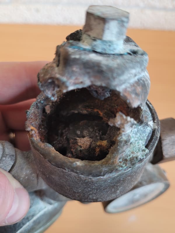
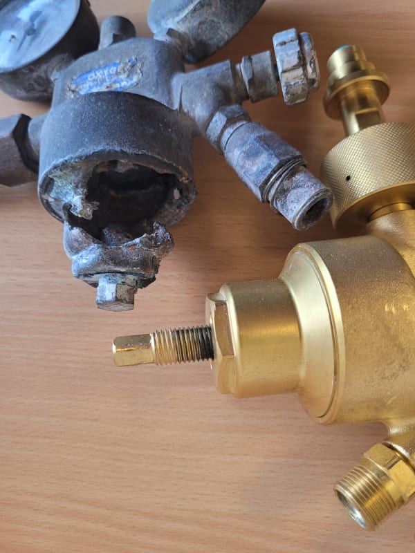
I have attached two images of a pressure regulator that ignited a while back, causing severe, permanent, bodily harm to the two operators in close vicinity. The 2nlet pressure was approx 200 bar, and the outlet pressure was 10 bar. Cause of ignition: poor operator handling in combination with particle impact.

20220824_133155_cxonfs.jpg
20220824_133340_eacx6i.jpg
 
During air separations plant operations training, the plant manufacturer cautioned us that clothes can catch fire just by standing in front of a high velocity jet stream of pure O2. Luckily, this didnt happen to any of us.
We only use SS304L or 316L for all equipment and piping materials in pure O2 service. High pressure O2 recip compressors have pistons with non contact labyrinth seals, no piston rings.
 
georgeverghese: Oh absolutely! Any area where an oxygen enriched conditions can be reached is to be taken very seriously. Take hospitals for example; a tiny leak from an oxygen tube can easily make so-called "non-flammable" textile materials burn fiercely.

Interesting what you say about the O2 recip compressors, I didnt know that!

I'm swerving off topic here but it is an interesting discussion:
When it comes to materials my company have been using 316L for high pressure oxygen piping since the 60s, with no accidents. The exception is pressure regulators, fittings, distribution manifolds and filling adapters. In these applications nickel-copper alloys, brass or Monel 400/K-500 is a must. That being said - in the last couple of years a lot of the larges gas companies have started phasing out all use of stainless steel due to oxygen safety. I wouldnt be surprised to see all of the stainless steel piping being used today being phased out within 5-10 years in most of Europe. At least that is the indication that we are getting from our customers as of late.
 
Status
Not open for further replies.
Back
Top