Continue to Site

Eng-Tips is the largest engineering community on the Internet

Intelligent Work Forums for Engineering Professionals

  • Congratulations GregLocock on being selected by the Eng-Tips community for having the most helpful posts in the forums last week. Way to Go!

Advice Needed with shearing occuring adjacent to weld

Status
Not open for further replies.

duffman1278

Nuclear
Aug 29, 2011
9
I am investigating solutions for my company on a weld that they have had failures with in the past occurring next to the weld. In the picture below it doesn't show any cracks but I highlighted where the incident occurs at.

I'd appreciate some suggestions as to ways to prevent this because on an up coming product, the crank will be experiencing much greater torque than the sample part I have shown in the picture and so we'd like to avoid this. My only thought was to either preheat the parts before welding or post heat treatment? Both seem like slow process's that would hold up the mass production of these parts.

I would like to bolt down the hub that the sprocket mounts to (the picture shows a pulley but this is for a different product) however because of the limited space that we have to work with, it seems like we have no choice but to weld it.
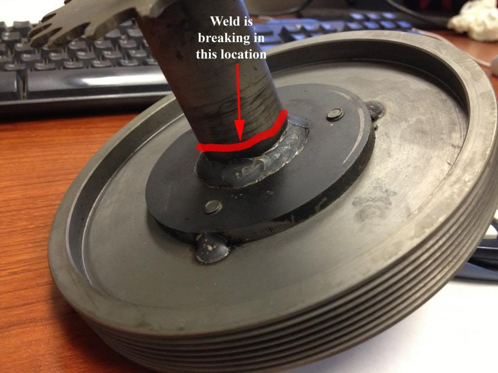
photo_zps660b6556.jpg
 
Replies continue below

Recommended for you

You have something rotating that will never be concentric combined with a weld configuration that is crappy in fatigue.

It's gonna break.
 
You didn't mention the type of base metal or the state of heat treatment. Was the material hot rolled, normalized, forged, or what?

You also failed to mention whether the failures were due to fatigue or if they twisted (torque) and sheared or if the failures were at the toe of the fillet or in the HAZ or in the unaffected base metal.

Details my friend, we need details.


Best regards - Al
 
At the moment I do not know if it is hot, cold rolled, etc. I have asked the supplier to inquire about that information.

My mistake [rednose] It fractured at the HAZ which leads me to believe it's over stressed since it's more than likely not a sensitive material to weld. Has to be .04% or less carbon content steel. And if there was a high level of hydrogen it would have cracked right after the welding, whereas this is cracking during usage. Therefore it is fatiguing.
 
The welding process appears to be GMAW, which is usually considered to be a low hydrogen welding process. That being said, the welding process isn't the only source of hydrogen. The welding procedure should address cleaning to remove all hydrocarbons and cutting fluids, etc. which could be sources of diffusible hydrogen. The delayed cold cracks, i.e., underbead cracks, could easily take time to incubate. Once initiated, it could take more time to grow to a critical size. Right in the HAZ is where I would expect hydrogen assisted cracking to be located. Without sufficient preheat, the carbon content or the carbon equivalency could be considerably lower than the value you mentioned and still be susceptible to some undesirable microstructures.

I would expect fatigue cracks to initiate at the toe of the fillet weld. That is where the notch effect is the greatest and it is the location where you can expect to find minute oxides extending into the HAZ along the weld interface. While the shaft is rotating at relatively low rpm, it would not take long to accumulate 10 000 cycles, the point where a number of welding standards require the designer to consider fatigue. Small eccentricities or wobbles are all that is needed to initiate fatigue in the assembly.

One corrective step you could consider is to contour the weld after welding to produce a concave face and refuse the toes of the weld before contouring to melt out the oxides at the toe of the weld. Contouring would reduce the notch effect of the geometry at the toe of the fillet weld. Any undercut, regardless of how minute can be a significant stress riser when fatigue is a consideration.

I would also check the carbon equivalency to verify sufficient preheat is being used to prevent undesirable microstructures in the heat affected zone. I suggest you review Annex I of AWS D1.1 to determine the required preheat based on the chemistry of the shaft material.

You should also check the cleaning process used before the pulley is welded to the shaft. Cutting fluids used during machining or cutting operations are notorious for containing sulfur compounds and hydrocarbon. Both are bad actors when diffusible hydrogen is suspected of being a factor in weld failures.


Best regards - Al
 
You need to know the chemical composition and heat treatment of the materials being joined otherwise you are in the dark.
 
I took the liberty of brightening your picture.

Your image and comments indicate the cracks are likely to occur away from the actual weld. Is that right?

Do you have any pictures of both fracture surfaces of some failed shafts?

I'm guessing there are bearings on that shaft somewhere. Where do they sit, and how are they retained?

the scale of the part is hard to judge. I'm guessing the bolts are 1/2 inch or smaller. Is that right/
Is that a poly-v belt sheave/pulley?
 
 http://files.engineering.com/getfile.aspx?folder=08239ab6-d173-4981-b041-26c6610e27ee&file=photo_zps660b6556_gamma.jpg
.04% Carbon steel is very very low carbon steel. It's probably not that. But you really need to find out from your supplier what the material is because that will make a huge impact on what the requirements are for welding the shaft. You may need to do a somewhat elaborate pre-heat and post-heat to keep cracks from forming (which may be invisible until stressed, not all cracks "pop" on their own.

If you can give us the shaft material, shaft diameter, your filler wire specifications and the welding parameters.
 
There is some type of saw-toothed part showing at the top of the picture. What is it used for?
 
What about eliminating the weld by using a forged shaft with an upset flange, similar to axle shafts, etc.? The sprocket on the other end could be joined to the shaft by splines, polygon shape, threaded fasteners, etc. Or possibly flip it around where the splines, etc. are on the pulley side.
C-clip%20Axle%202.jpg
 
There also appears to be rub marks on the shaft. Bearing related?
 
I hate to say it like this, but the amateurish nature of your questions and comments leads me to believe you may not need to be working on such a project. (I mean amateurish in regards to mechanical design.)

Most likely cracks due to cyclic stress. That type of connection is prone to it, and there should be relatively simple solution to someone with appropriate mechanical design knowledge.
 
Looks like Duffman has not been back since Feb 15.

I took the 'saw tooth part" to be a chain sprocket further along the shaft, >>perhaps<< at the end, with all the support bearings in the middle, but the assembly is sitting on the desk with a tilt as if a stub shaft extends beyond the pulley/sheave, so there might be a bearing seat there. Lots of missing details to be sure.
 
I wonder if a smaller weld may have been sufficient. If the material was not normalized, I can see that such a large weld could have drawn the carbon out of the adjacent area and reduced its strength. What were the weld details? Was it stress relieved after welding? Could you have used bosses around the perimenter to strengthen to reduce moment stresses?
 
From OP's profile as of Monday Feb 25. "My last login was on Friday, February 15, 2013."
 
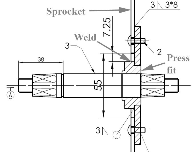
Whoa, so many replies. Sorry about that guys,been on the road for a bit. Someone mentioned it here, but we're going to go with a press fit sleeve onto the hosing and then the sprocket will get welded onto the bushing like shown below.

I wasn't able to get the composition of the material. The supplier is lagging or ignoring my emails.

asdasdsa_zpsa732e20a.jpg
 
That's an awful lot of parts just to attache a sprocket to a shaft.

And your weld symbols do not appear to conform to any standard.

What do you think the load path is?
 
Keep in mind this is for a consumer product, not nuclear or aerospace standards. Just to throw that out there. It makes a for a huge difference in available options to go about this issue. What do you mean by load path? Sounds like a civil/architectural term
 
Status
Not open for further replies.

Part and Inventory Search

Sponsor