swazimatt
Civil/Environmental
- Aug 19, 2009
- 277
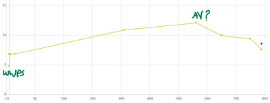
I am reviewing a design of a ww rising main. The pipe is 150mm dia and the pumped flow is in the region of 30 l/s. total rising main is 885m
At the request of the client the discharge location is about 233m past the last high point and about 4.5m below this highpoint (this is the only high point and the WWPS is about 9m below this point). Not my preference but they have their reasons
The pipe will be discharging into the gravity network.
rough profile attached
The designer has placed an airvalve at the high point and i was initially concerned about the flow into the pipe through the air valve every time the pump stops. When the pump finishes a cycle the pipe will drain from the high point to the gravity network. I feel that i might get away without an air valve as the pipe would slowly drain from the open end. As the falling portion of rising main falls less than the rise i do not believe there is the risk of siphoning, but this raises my 2 queries
1. when the pump turns off will the flow in the pipe have enough momentum to create a siphon and continue flow through the system (including the submersible pumps and non return valves)? Is there a way to check this?
2. If i add an AV at the high point i know this will break any siphoning and allow ai into the pipe, but if this exceeds the allowable flow into the pipe will it create negative pressure in the pipe (i doubt it as it is less than 10m(rounded) vertical head) how do i calculate the max rate the pipe would drain? I have tried Hazen williams and find it drains at a max of 31 l/s but not sure if this is correct. I know the AV orifice will restrict flow into the pipe, and "control" the rate of draining, but how / what formulae should i use to calculate this. I have had someone tell me about a similar situation where the air flow through a single air valve resulted in a whistle similar to a steam train every time the pipe drained
thanks
(part of writing this has solved some of my other queries!)