Eng-Tips is the largest engineering community on the Internet

Intelligent Work Forums for Engineering Professionals

  • Congratulations waross on being selected by the Tek-Tips community for having the most helpful posts in the forums last week. Way to Go!

airfoil surface

Status
Not open for further replies.

ArashIKamangir

Mechanical
Mar 29, 2007
8
0
0
IR
hi there
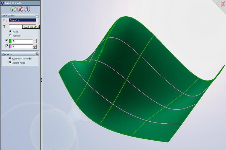
i'm working on an imported airfoil surface in igs format.the surface curvature is somehow discontinous.i want to modify the surface to obtain a smooth surface preserving the original design.
i have tried to obtain several intersection curves using planes intersecting the surface, modifying the resulting curve using simplify curv,and finally lofting between intersection curves but the result is still unsatisfactory.
please help
thanks
 
Replies continue below

Recommended for you

Its hard to tell you what to do... You have done many of things that I would have suggested. Maybe its how your building your Sketches. Try using a fit spline if you are looking for a continous surface. I would think lofting with a number of profiles and guide curves would allow you a smooth design. But you might just try replacing the surface once you get a suitable surface that you like...

Make sure your Image quality is up to, otherwise it will make the surface look more squared.

Regards,

Scott Baugh, CSWP [pc2]
faq731-376
 
That's what I was thinking, too, Scott.

If you use the Fit Spline feature, you have control as to how tight the spline will "stick" to your under-lying sketch segments. A tighter spline will have smaller minimum radii and be less "rounded", but more accurately represent the segments beneath. The opposite is true for a more loose fit.


Jeff Mowry
Reason trumps all. And awe transcends reason.
 
Instead of loft, try boundary surface. Can you post pictures or the model....it's really hard to help with out seeing the model.

Jason

UG NX2.02.2 on Win2000 SP3
UG NX4.01.0 on Win2000 SP3
SolidWorks 2007 SP2.2 on WinXP SP2

 
I am very interested in the answer to this question as well. I have been going through and drawing curves on different reference planes to try to get a profile of the airfoil and loft between each of the ribs to get my solid model but it is taking quite a while and does not appear to be giving me the most accurate shape of the airfoil.
 
You may want to just get the airfoil data from VisualFoil or some other airfoil database (theres hardly any airfoils that aren't documented by either NACA/NASA), dump it into Excel (you may have to manipulate it with notepad or something). Use the Curve from XYZ points and create the extrusion/loft.

The other option, if its a surfaces, fix it up and knit them up to create a body, if its an imported body...just create planes at different points and use the section view to section at the plane, create sketches on those planes and convert the sketch entities.
 
Tried using the Face Curves command? This will extract UV curves from faces to create 3D sketches.

UV-1.jpg


hope that helps

-L@P.I.D.

Work: Dell PW690-Intel Xeon E5345 2.33GHz-PNY QUADRO FX3450 Drivers 77.56-4GB DDR2 FB-DIMM 667MHz ECC-80GB 10K-250GB 7.2K-Win XPx64-SW2007 SP2.2-RHINO 4.0 SP0
Play: Intel X6800 Core 2 Extreme - Asus P5W64 WS Pro i975X -2GB Corsair XMS-EVGA NV7900GTO(Mod. GTX Bios , FW93.71)-74GB Raptor-250GB WD Caviar
 
Status
Not open for further replies.
Back
Top