Continue to Site

Eng-Tips is the largest engineering community on the Internet

Intelligent Work Forums for Engineering Professionals

  • Congratulations SDETERS on being selected by the Eng-Tips community for having the most helpful posts in the forums last week. Way to Go!

Airframe Shell FE Modeling

Status
Not open for further replies.

sarclee

Mechanical
Jan 14, 2022
105
Hello, want to check in airframe assembly such as fuselage modeling, how do you handle the connection between the skin, frame or longeron? Just to merge them or using rigid element connector?

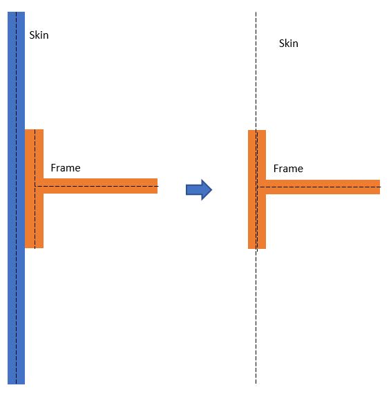
If we merge the frame to the skin, are we still model all parts as midsurface? There will be gap between parts, right?
 
Replies continue below

Recommended for you

Do not use rigid elements to connect.

Usual approach is to model skins at midplane and move the frames and stiffeners to the skin node locations.

Or use solid shell elements in Abaqus for skin.
 
@SWComposites, thanks!

If we plan to extract the load, RBE2 or mpc still not advisable to use to connect the frames to the skin?

Is the picture below correct?
skin_ph5kfw.jpg
 
Picture is correct.

I’ve never used glued contact. If you want to use it, build and run some simple test models to be sure it does what you expect.

Avoid rigid elements; they can create all sorts of havoc in the model.
 
no one (AFAIK) worries about the fuselage skin mid-plane, the impact on the section properties and the loadpaths within the structure are negligible.

you have the OML of the fuselage, use this for the skin. Sure you could model the mid-plane, but meh.

use the skin surface (nodes) as the frame outer cap and the stringer reference. You "can" model the stringers as offset from their nodes (on the property card), but this adds a lot to he model computation for little gain/difference. ie use one set of nodes for the skin, the frame outer caps, and the stringers/longeron outer caps.


another day in paradise, or is paradise one day closer ?
 
On cars to get fatigue life estimates at one time we modelled each spotweld using a proprietary spotweld model. The CAD of the body does not show the spotwelds, they are held in a separate table. A preprocessor then runs through this list automagically inserting a spotweld model at each location.

Cheers

Greg Locock


New here? Try reading these, they might help FAQ731-376
 
Thanks @SWComposites, rb1957 & GregLocok!

So it is not necessary to midsurface for every parts. We can offset the properties for merging the nodes at connection. I am just thinking whether to merge all the connection then extract the element forces to calculate the number of fasteners or just create the connector based on the pre-defined fastener location? I have no confidence on the pre-defined fastener location as there is no heritage information....

About rigid element, if we extract the loads not looking at the stress, why not?

Instead of using RBE2, I am also thinking to use CWELD/MPC.

 
please don't model each fastener. The usual (AFAIK) is to take the shear over a length times fastener pitch for shear on a fastener.

using a FEM for loads is ok, but remember to add things. If you are using a typical GFEM with a single element of a stringer bay (frame-to-frame, stringer-to-stringer), then pressure is not well represented. This modelling has the advantage of nicely fitting subsequent analysis, particularly diagonal tension. If you use several element per bay, then the skin will detect pressure "better" but you'll have to remember the mid-bay nodes (and their need for support) and model the stringers as beams, and you'll have to think about combining elements to make a frame bay panel (use the average ? use the highest ??).

another day in paradise, or is paradise one day closer ?
 
@rb1957, I try not to ... perhaps only the critical area that I focus on the joint area using 3D not for global model.


If I model all parts in midsurface, is moving the frame to the skins/ panels usual approach?

123_g0d084.jpg
 
Its a typical approach for a transport fuselage.

What are you trying to model? That picture is not a fuselage.

The FEM should give you element loads. From that you create free body diagrams of the bolted joint connections and determine fastener loads and bypass loads by hand.
 
@SWComposites, it is equipment box. I randomly create a geometry for discussion.
 
"focus on the joint area using 3D not for global model" ... then why post a question inferring you're interested in a GFEM issue ?

Modelling a joint is a very different matter ! Modelling with 2D and 3D components is also very different.

Are you working in an office (and have someone there to help you) ?

Are you looking to learn something (just for the heck of it) ?

Both issues above (modelling a joint and modelling with 2D and 3D components) are going to be very difficult to explain, particularly if English isn't your 1st language
(that's more a comment on my ability to describe highly technical things ... someone who may not understand colloquial terms like "lick of paint" or "tim o'shenko").

have you gone through any of the FEM texts that are available ? which ??

another day in paradise, or is paradise one day closer ?
 
@rb1957, I'd been doing GFEM using nastran in the past. we merge the nodes at connection area or create CFAST. But now I am using ansys which allow me to use linear contact easily but there are pro and con. So, I like to get some opinion and see if I will miss out any important points when I change to different method of modeling using new software.
 
it'd've nice to have mentioned ANSYS earlier, maybe post on the ANSYS forum.

another day in paradise, or is paradise one day closer ?
 
@greg, re spot welds ...
i wonder ...

1) if spotwelds are less plastic than metal fasteners, and so less forgiving in load transfer areas ?

2) if spotwelds are "optimised" in auto design (to reduce cost ?)

3) if design requirements have gotten more intense over the years, requiring more analysis (with little improvement in safety ?)

4) if production cost reductions are driven Engineering into more anlaysis (with decreasing marginal gains ?)

5) if someone (Japanese, German ?) started a trend, and the rest jumped on the bandwagon ?

6) all of the above ??

another day in paradise, or is paradise one day closer ?
 
Sarclee. Google Ian Taig's "Aircraft fem notes". From memory it addresses this question.
 
Status
Not open for further replies.

Part and Inventory Search

Sponsor