Continue to Site

Eng-Tips is the largest engineering community on the Internet

Intelligent Work Forums for Engineering Professionals

  • Congratulations waross on being selected by the Eng-Tips community for having the most helpful posts in the forums last week. Way to Go!

Airlock in a double bag arrangement

Status
Not open for further replies.

aaansari97

Mechanical
Aug 1, 2021
11
Hello all,

I'm working on improving an existing system that consists of 2 water bags hung on an elevation below a peristaltic pump. A single solenoid valve controls the flow through both tubings (Image attached).

1. Upon repeated operations of this arrangement, we observed that an airlock locks flow from one bag (bag 1) and the pumps starts to draw liquid from the other bag only (bag 2). This is opposed to our intention of equally draining the bags.

2. Also, we have observed that as liquid level in bag2 falls (because of fluid flow), the airlock ultimately gets sucked into the pump system and discharged. This is good news but the airlock shouldn't have occurred in the first place.

The issue is that our machine software is built on the assumption that liquid will be drained from the bags approximately equally. Also, with this bag arrangement, we believe the machine's mechanical behaviour has become unreliable since sometimes when the airlock doesn't occur, the bags are indeed drained equally.

We have decided to change the pump suction arrangement entirely to bypass this problem and added an intermediate bag for deaeration purposes. However, my seniors are demanding that I give them a reasonable physical explanation of the issue and its causes before we change the design.

Air coming into the tube is no problem and is an expected occurrence. However, airlocking is an issue and I have not been able to come up with a good explanation. I understand that airlocking reduces the elevation head of water (height of airlock * water density* gravitational acceleration [rho*g*h]) from the airlocked bag at the junction but why can't we simply suck out the problematic airlock?

Any help will be appreciated. Please note that the pump is above the bags and liquid under question is water.

Thanks!
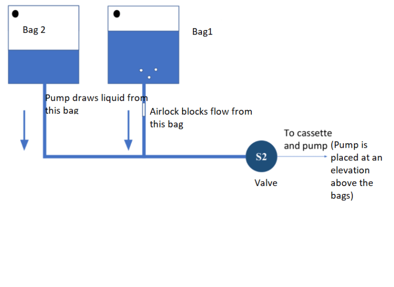
Screenshot_2021-08-01_182914_tbm1et.png
 
Replies continue below

Recommended for you

Air lock occurs where there is no pressure difference across the bubble.
With no pressure difference in a branch between any two points in a branch, flow in that branch stops.

In the diagram I copied ...

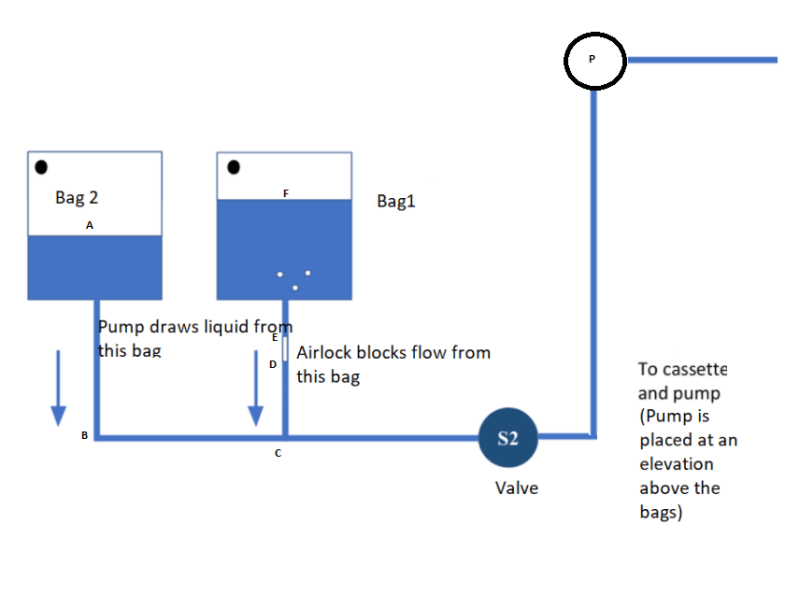
Head from A to B - head from C to D is equal to the head from F to E.
The pressure immediately above the bubble = the pressure immediately below the bubble
(assuming the bubble weighs next to nothing).

When there is an air bubble at DE, the head from bag 1 acting at C is "neutralized", it is already balanced at D with the head from A to D, so only the head of bag 2 controls the pressure at C. As the level of bag 2 decreases, that lowers the pressure at point C.

When Bag 2 empties enough to reduce the pressure at C to a lower value, such that head AB - head CD is less than head FE, flow from bag 1 will start again. Lowering the elevation of bag 2 may also help keep the pressure at C a little lower, thereby enabling a little more flow from bag 1.

Untitled_ycszuq.png


You might improve the performancemance if you can move the connection point C to the valve and put the valve immediately adjacent to the pump. No guarantees. You might also improve the performance by lowering the pump as much as possible, preferably below the level of both bags. It is possible that a larger pipe diameter, connecting bag 1 to D or C may help, but it may also drain bag 1 faster.

Contrary to popular belief, pumps do not suck liquid from the bags. A pump can lower its inlet pressure enough that the head provided by the bags becomes sufficient to move their contents to the pump. Lowering the pump, or raising the bags as high as possible will help.

Note: There may be some important capillary surface tension effects that I am ignoring in the above.

So, does this air bubble form at C and move up to DE? Where and why is it forming? Is it from air entrained in the water, is it from disolved air in the water coming out of solution, is it from low pressure at C.
 
One additional factor - surface tension. Even if there is a differential pressure, if the tubing supports surface tension with the liquid an air bubble can plug the line. As one who built a water level with thin tubing I found that plain water was nearly impossible to work with - since it's a tool I could add a portion of isopropyl alcohol to decrease the surface tension to allow the bubbles to be released.
 
Oh right. How did I manage to call that "capillary" tension? [ponder] I don't know.

 
Have you tried putting the T between the two bags? Then, at least, you'd get bubbles on both bags, if at all.

Your drawings don't seem to make much sense as to where the air is coming from, although you state that it's "expected."

TTFN (ta ta for now)
I can do absolutely anything. I'm an expert! faq731-376 forum1529 Entire Forum list
 
Hello and thank you all!

To answer your questions:
1. So, does this air bubble form at C and move up to DE? Where and why is it forming? Is it from air entrained in the water, is it from dissolved air in the water coming out of solution, is it from low pressure at C.
>>We use sealed liquid bags from a renowned medical supplier. Bags inevitably contain air bubbles (maybe due to agitation when handling?)
Also, when we first turn on the pump, the air in the tubing of bag 1 is somehow trapped between liquid whereas liquid flows freely from bag 2.

So, this air might be coming in from the bags or simply be the air that existed in the tubing and got trapped as the system began to draw liquid from one bag before letting the air be removed first.

To give you more details, we're using a internal-dia 3.5 mm rubber tubing.

@1503-44, I understand much of what you're saying except this statement.

@IRstuff, can you please explain what this means?

Thanks!
 
If you want equal flow and emtying the same then you need to make everything as equal as you can.

As you've drawn it Bag 2 has more / longer tubing than bag 1. Now that may be the way you've drawn it but without dimensions we don't know.

If indeed those tube are actually vertical the only thing I can see to stop that bubble going up is that the tubing is too small and you're getting some sort of surface tension issue that is stopping it going vertically up.

Is your tubing all vertical? Do you have a picture?

Placing the pump above the bags ( how far above?) means your piping system may well be operating below atmospheric pressure, hence encouraging any dissolved air to come out. Can you lower the pump to below the level of the bags?


Remember - More details = better answers
Also: If you get a response it's polite to respond to it.
 
(notice the pre-flush with alcohol)

Approaches used in patient treatment:
It does get me wondering if a somewhat coaxial item would prevent blockage - like a piece of PTFE (Teflon (TM)) or other suitable solid plastic fiber inserted into the tubing. This would prevent a bubble from completely sealing off the flow since the surface tension would pull the bubble into a minimum surface, forcing the insert off-center. Held against the wall by the bubble, the contact point has an infinite curvature which the bubble cannot have - the surface tension is finite. Therefore there has to be a gap through which the water will flow.

I don't see PTFE in a small diameter rod, but it is available in a small diameter tube which would work the same -
I might have tried that on the water level, but I think pushing a plastic fiber down 50 feet or so of 1/8th ID tubing is more challenging than the alcohol was.
 
this statement.
(When there is an air bubble at DE, the head from bag 1 acting at C is "neutralized", it is already balanced at D with the head from A to D, so only the head of bag 2 controls the pressure at C. As the level of bag 2 decreases, that lowers the pressure at point C.

Means .really nothing more than the obvious.. no flow from bag 1, so it is essentially hydraulically isolated from the rest of the pipe.

Normally in a free flowing system, heads from both A and F branches are always balanced and correspond to liquid levels in the bags. If they were not, flow would start from one bag to the other and the liquid levels would move up and down until liquid levels in each were nearly the same and the final head at C would be the result of that interaction. Your diagram shows what should result in a high flow from bag 1, to bag 2, or to the pump, yet bag 1 is not flowing anything. That indicates the higher liquid level we see in bag 1 is not affecting flow to C, as is also indicated by the stationary bubble. If flow is not occurring in F-C, and the bubble is not even moving up and down even just a little, then the system is not "feeling the effects" of the head in branch F-C at all. If that is the case, the pressure at C must be almost only the result of the head created by bag 2 alone. The effects of liquid level at C from bag 1 must be much less than the effect of bag 2. Bag 2 is essentially controlling all action in the pipe to valve and pump.

You then see that happen, as the bag 2 level has to drop and greatly lower the pressure at C before bag1 pressure becomes greater and starts moving the bubble down..

Does that make sense now?

The zero weight of the air bubble and surface tension greatly reduce the effect of bag 1 fluid level to the pressure at C.
 
I think there is a lot of merit to 3DDave's comments. You might have better success in preventing the bubble, or handling it in some way. I just have that idea in my head of increasing the inlet diameter of the pipe at F-E as helping somehow. It seems that a very small reduction of bag pressure is enough to initiate bubble formation.

 
I did not look to the previous posts ..

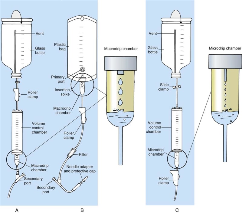
My suggestion will be, JUST WRITE ( SERUM INFUSION SET TUTORIAL ) and search the web to see the flow mechanism .

One of the possible outcomes ;

SERUM_INFUSION_SET_80323086547_unsbxt.jpg


Apparently you need drip chambers and clamps to controll the flow..
 
That's what I was thinking of ... like the "microchip chamber".

 
Even with the drip chambers - nursing staff have to smack the upper part of the tubing to force a bubble to move. The drip chamber simply means that no bubble introduced into the bag can easily migrate further.
 
I imagine so, but it shouldn't need to move, if the fluid is passing by. A bubble trap should help.

 
The bubble trap only helps if the bubble moves into it. I had, in my water level, up to several inches of height difference because of a bubble in the horizontal section. Fluid won't go by the bubble if it is held by surface tension - having personally experienced this, it is maddening. I had previously gotten an adapter for the garden hose and that proved nearly impossible to remove all the air from - regularly getting an inch difference because air had collected somewhere. Too large for surface tension, but the hose would not lie completely flat so a bubble would get to the top of some rise and stay put and creating a buoyancy imbalance.

The smaller vinyl tube let me see the bubbles and I spent hours trying to get them to move, but small bubbles would stick to the walls waiting to coalesce into one large enough to block the flow. Since it was so long, a bubble might have 30 feet to go to exit and shattering a blocking bubble by impact would just make tiny bubbles that stuck again to the tube wall. Rinse and repeat until I turned to alcohol. Isopropyl alcohol that is. And then the little bubbles didn't stick anymore.

 
Thank you so much everyone!

I think we were ignoring surface tensions effects.

We cannot make any changes to the tubing since it is part of a disposable set that has already had several iterations and in case we are forced to change it, we'd rather simply change the bag arrangement.

I think we have enough information for now.

Thanks!
 
One easy option might be to add a tee at the base of the pipe at the junction with two valves and flush out the pipe until you can't see anymore bubbles?

Should only be a small amount lost. Just make sure you do it before turning the pump on otherwise you might suck in air instead of flushing it out...

Remember - More details = better answers
Also: If you get a response it's polite to respond to it.
 
Note the roller clamps in the above diagrams. These are used to sweep bubbles through the system upon initial set-up.
 
Status
Not open for further replies.

Part and Inventory Search

Sponsor