Continue to Site

Eng-Tips is the largest engineering community on the Internet

Intelligent Work Forums for Engineering Professionals

  • Congratulations MintJulep on being selected by the Eng-Tips community for having the most helpful posts in the forums last week. Way to Go!

AISC Design Example: Query on flexural strength of connection plate 1

Status
Not open for further replies.

AK4S

Structural
Jan 2, 2015
98
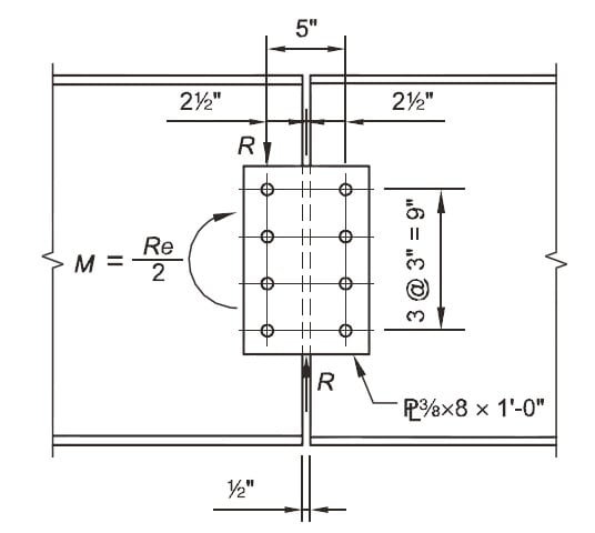
I am looking at the AISC Design example (EXAMPLE II.A-20 ALL-BOLTED SINGLE-PLATE SHEAR SPLICE) attached with this post.
On Page 3 of the PDF, to calculate the Flexural Yielding of Plate, the equation Mn =Fy*Z is used.
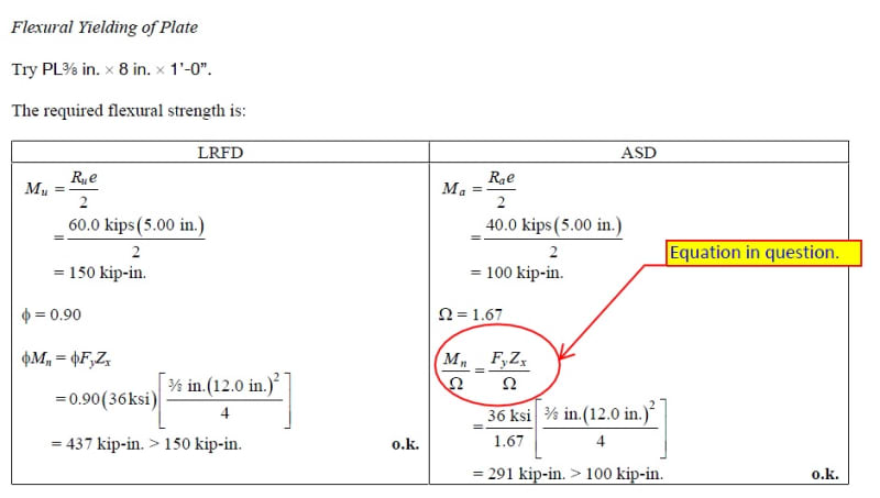
Untitled_kggccp.jpg


Per AISC Manual (14th Ed) Chap 9, for Connecting elements subject to flexure, the available strength is determined by AISC spec section J4.5 and Chapter F.
Based on my understanding, for the connection plate one should refer section F11 (rectangular bars subjected to flexure).Where, the nominal flexure strength Mn = Fy*Z <1.6 My. Also the Lateral Torsional Buckling limit state is to be checked.

However, the Design Example does not include the 1.6*My upper limit nor checks for LTB. Any suggestions? Am I missing something?
 
Replies continue below

Recommended for you

It's because it's a rectangular plate. Shape factor for a solid rectangle is 1.5 (Z/S), so it can never be more than 1.6My. That section also applies to rounds, and circles have a shape factor closer to 1.7. So for rectangles, it's Mp, for rounds it's 1.6My.
 
@phamENG: Thanks for the clarification.
What about check for LTB, isn't it applicable?
If so, what would be the unbraced length of the compression region, Lb.
Is Lb= unbraced length of the plate between the bolt holes = 5"-(7/8+1/16)" =4.0625"?
If so with d=12", t=3/8". Lb*d/t2 =346.6 , 0.08E/fy=64.4, 19.E/fy =1530
So, 0.08E/fy < Lb*d/t2 < 1.9E/fy

Then Wont the check for Mn using equation F11-2 (AISC 360-10) for LTB condition be required?

Untitled_twaa4v.jpg
 
Technically, I guess you could say yes. But consider the definition of unbraced length:

AISC F11.2 Lateral Torsional Buckling said:
Lb=length between points that are either braced against lateral displacement of the compression region, or between points braced to prevent twist of the cross section.

The clamping force of the bolts will effectively bring Lb down to about 0.5" - the gap between the plates. The only torsional concern here is more of a global one as it relates to the torsional stiffness of the splice and how it restrains twist in the connected member.

Have you run the rest of the LTB calculation for this? If so, you'll notice that you only get about a 7% reduction if you consider LTB as you have above. So you can say it's a judgement call - if I'm at less than 50% utilization, I'm not going to sweat a 7% decrease in capacity. Now, if I were maxing this thing out - sure, I'd probably run everything to make sure there wasn't some unusual weakness in the design.
 
Sure, you can look at F11 you could check the plate for LTB.

What's your Lb? 5"? With the nuts and washers and such, I'd say it's more like 3". I don't think LTB is going to control with an unbraced length of 3".
 
@phamENG & JoshPlumSE: Thanks for your inputs.
Yes, going through the LTB check using my Lb values gets me a 7% reduction for this example.

I was going through the checks for a similar connection where the gap between the members is larger (4")and the plate is deeper. For my case, using the Lb=length of the plate between the bolt holes, and going through the LTB check, the flexural strength is limited by Mp. so I am good.

I was being conservative on the length of Lb. Do not have a feel of generally how much I can reduce based on clamping force of the bolts.
 
If you need to check LTB, I wouldn't reduce it. In fact, I would use center to center spacing. I was just pointing out the reason that I think AISC excluded it from the example. It's a matter of engineering judgement.

Consider a beam made up of just a single rectangular plate bent about its strong axis with a UDL on it, and gradually increase Lb. Watch the predicted behavior of the plate. Try to get a feel for when LTB will start to control the design. Then vary the plate and the amount of load and try again. After a while, you'll get a feel for what to expect and when you need to do that check and when you don't.
 
Noted. Will do some sample runs to figure out when LTB governs. Thanks
 
Status
Not open for further replies.

Part and Inventory Search

Sponsor