Eng-Tips is the largest engineering community on the Internet

Intelligent Work Forums for Engineering Professionals

AISC - Lapping Plates subject to Bending and Axial Force

Status
Not open for further replies.

MGaMart

Structural
Aug 23, 2016
50
0
0
CA
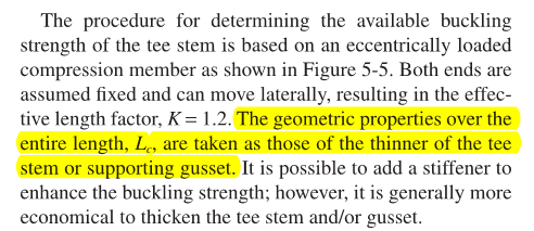
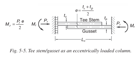
Looking for some insight into a matter. Looking at 'Design Guide 24-Hollow Structural Section Connections' (which is readily available online), section 5.2 talks about the procedure for checking buckling strength of a tee stem. Eq. 5-1 and 5-2 show the generic formula for members subject to axial and bending forces. Eq. 5-3 and 5-4 are manipulated to provide the maximum axial force on the basis that the moment, M = P*e/2. This suggests that the moments at each end are equal (as shown in Figure 5-5) and that each plate is required to resist 1/2 of the moment induced due to the eccentricity. In the event that the lapping plate thicknesses are not equal to one another,could Eq. 5-1 and 5-2 be manipulated to reflect the rigidity of each plate?... meaning the thicker plate resists a greater percentage of the moment induced by the eccentricity. Aside from the need to derive the maximum axial force equation from Eq. 5-1 and 5-2 and checking it against the respective plate, it seems this would a more efficient approach to better reflect how the plates resist bending (when the thicknesses vary).

As an generic example, if a 1" gusset plate joined with a 1/4" plate, could the 1" gusset resists P*(3/4*e) and the 1/4" plate resist P*(1/4*e) (the fractions listed are made up, not to reflect the rigidity each plate would have relative to the other). The design guide (and any other literature I've found) provides examples which assume the lapping plates are equal in thickness (not very representative of real life connections)

Many thanks for any input on the subject.
 
Replies continue below

Recommended for you

Can you achieve a similar result by developing your moment from an FBD of each plate, with load applied by the bolts at the faying surface?

Also, I'm curious what is causing your plates to be unequal thickness. I would have assumed the equal thickness assumption to be pretty good (for new design at least, maybe not retrofit).
 
I'm not sure I understand your statement. The moment induced as a result of the axial load jumping from the centre line of one plate to the next would cause curvature in the plates, so the bending moment cannot be developed solely from the bolts that connect the plates together (since this is a case of out-of-plane bending). Using Eq. 5-1 and 5-2 are necessary to check the adequacy of the plates in bending. (If I've missed the mark on what you were saying, please let me know).

Unequal plate thickness may results from a few sources. In the case of using a WT section connected to the end of an HSS brace, the web of the WT may differ from the adjoining gusset thickness.
 
MGaMart said:
The design guide (and any other literature I've found) provides examples which assume the lapping plates are equal in thickness (not very representative of real life connections)

The examples may not consider different plate thickness but the method does. The method, by virtue of the definitions of Lc & K, treats the combination of both plates as a single compression member based on the thickness of the thinner part. See the highlighted portion of the snippet below. In this respect the method is, admittedly, conservative.

MGaMart said:
In the event that the lapping plate thicknesses are not equal to one another,could Eq. 5-1 and 5-2 be manipulated to reflect the rigidity of each plate?

I agree with your logic so long as you:

a) revamp the method to deal with each plate separately rather than as a combined unit and;
b) somehow account for the rather complex interaction of the two plates over the overlap length.

I'm not really sure how to go about dealing with (b). That, in itself, would send me back to the design guide method unless it was an existing situation and I were desperate.

Capture1_zq0mr6.png

Capture2_fitzge.png


I like to debate structural engineering theory -- a lot. If I challenge you on something, know that I'm doing so because I respect your opinion enough to either change it or adopt it.
 
Thanks KootK for attaching the Figure in this thread (for those who do not want to find the document online). The issue I'm struggling with is that in cases of bracing connections, the gusset on average tends to capture a significant portion of the unbraced length (in mostly cases due to constraints in geometry). If the gusset thickness is greater than the adjoining plate (the Tee Stem in the Figure), could the formulae be used to show this condition? The total moment created would be P*e, so each plate experiences a moment equivalent to the axial load P times one half its thickness (jumping the load from plate centre line to the faying surface (for the gusset, M_gusset = P*t_p/2). Although not correct, one could maintain the original unbraced length Lc applied to each plate to account for this alteration in applied moment (conservative in nature). Whichever plate governs with its respective internal moment dictates the axial capacity the plate combination can achieve.

This is my thought process at the moment...welcoming any opinions or constructive criticisms on the matter.
 
Status
Not open for further replies.
Back
Top