Wanna_be_SE
Structural
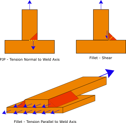
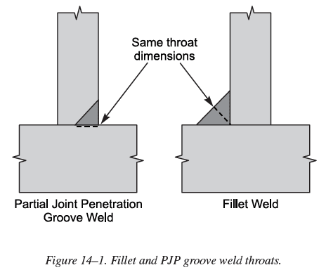
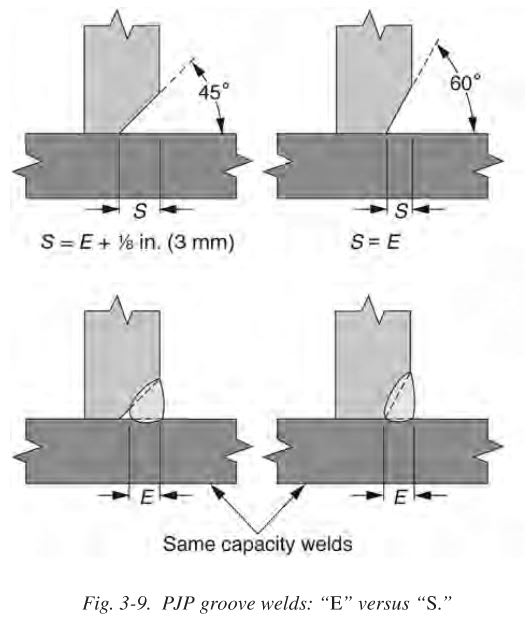
Recently I was doing some weld calc's using Spec section J, and discovered the Table J2.5 lists "tension" as a possibility for PJP weld joints. This made me scratch my head, bc it doesn't list tension as a check for CJP welds (bc CJP welds are governed by the base material) and that made sense but when I saw tension as a possibility for PJP welds, I don't understand why.
For most (if not all I think) weld calculations AISC basically always take a failure plane at the throat of weld (most conservative). Table J2.5 lists tension criteria for fillet welds as can be neglected, and I assume for the reason that weld rupture (tension failure) will never occur bc welds are typically (maybe always) stronger than base material, and the "path of least resistance" will always occur at the throat of weld - which is a shear failure, not tension. Therefore whether longitudinal or transverse loading on weld, taking a failure plane at the throat (AISC) will always give you a shear failure, so I beg the question why do PJP welds shown in Table J2.5 have tension listed? If anything, I would expect the CJP welds (butt welds specifically say in a plate) to have tension listed, but then again bc weld metal is typically always stronger than the base material, the base material would fail before the weld would (in a butt joint in a plate).
Someone mentioned that it could be based on the type of loading (perhaps bending, as opposed to shear or axial), but even in that scenario the weld failure plane that AISC tells you to take is always (to my knowledge) at the throat of weld, and again that's a shear failure. If you consider say an I-beam girder welded to an I-beam column, and lets say the connection has stiffeners and there's moment developed. The top flange would put that weld in tension under bending, however the failure that occurs IAW AISC is at the throat (shear failure), so I can not think of a situation that would warrant checking the tensile strength/stress in any weld. In this example I described, most likely it would be a fillet weld so Table J2.5 says to neglect tension, but lets assume (for the sake of argument) that the top flange weld is a corner weld (square groove with reinforcing fillet). That may classify as a PJP and therefore maybe you could argue check tension in weld....but that would go against the failure plane at throat, unless you said that failure plane at the throat was a rupture, and not a shear failure, but I've never seen that in any weld calcs I've done and with that being said you'd still have a shear failure at toe of weld - between weld and base material, so that would warrant almost like a block shear situation but in a weld (which just sounds crazy thinking about it). Maybe through some testing they've discovered there is a possibility and that's why it's listed, but kind of seems contradicting to some extent given the assumed weld area AISC always tells you to take.
Has anyone else ever wondered this, or am I the only one that honed in on the tension for PJP welds?