Eng-Tips is the largest engineering community on the Internet

Intelligent Work Forums for Engineering Professionals

ALE method for 2D metal cutting simulation in Abaqus/Explicit?

Status
Not open for further replies.

Nir_k

Mechanical
Apr 13, 2021
39
0
0
TW
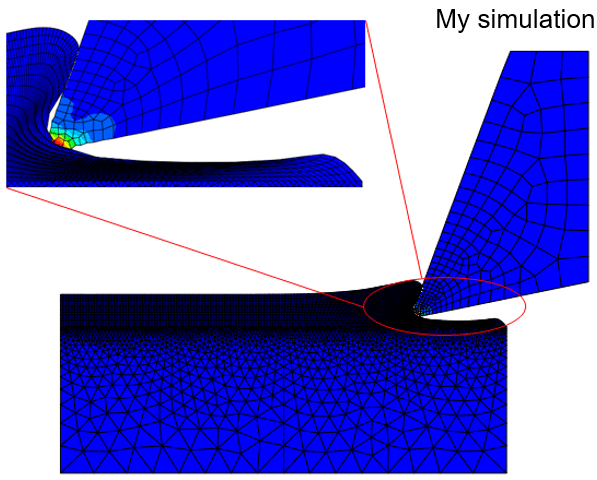
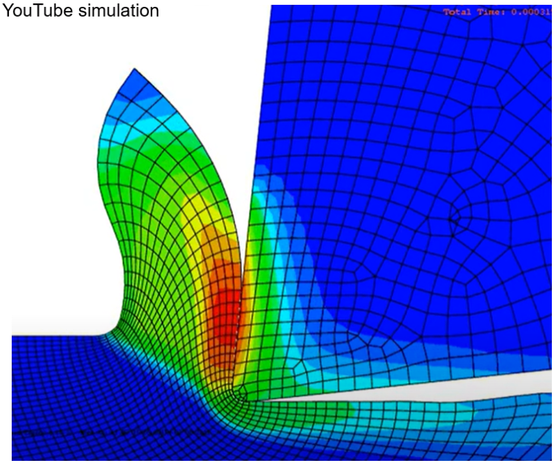
Hi everyone, I've recently been using Abaqus/Explicit to do a finite element simulation of 2D metal cutting using the ALE method, and I've seen a blogger on YouTube do a similar simulation( Still, his results are much more normal than mine. Doesn't ALE normally allow for mesh adaptation? Why is it that when I use ALE to simulate the cutting process, I can't get the chips at all? The tool isn't able to remove the chips from the workpiece. Rather, it only creates a bend in the area over workpiece. The mesh in the workpiece and tool contact area is not adaptive either; it is still badly distorted. I have followed in the Step module: Other→ALE Adaptive Mesh Domain→Edit, toggle on "Use the ALE adaptive mesh domain below" and click Edit to select the region ( undeformed chip region) and turn off the "distortion control" for the workpiece mesh. I also switch to the "ALE Adaptive Mesh Controls" and set. In the attachment is my .inp file. Where did I set it wrong? Please help me. Thank you very much!
ALE-mine_rqbup5.png
ALE-YouTube_erdvjk.png


Replies continue below

Recommended for you

If you want to actually cut the workpiece and see the chip formation, you need a damage model controlling the element deletion. You could use *SHEAR FAILURE, TYPE=JOHNSON COOK for that. It’s just a matter of finding the damage constants but it’s not a big issue for AISI 304 steel.
 
FEA way, My dear friend. Thank you very much for your answer. I read a lot of literature that the ALE method doesn't need to specify the chip separation criteria, so I didn't set up the damage model and turned off the element deletion. I saw that there is a blogger on YouTube ( who did the same simulation as I did, and the results of the cloud map show that he should not have set up the damage model and element deletion. As you can see in the picture above, the chips are separated from the workpiece in his simulation, and the mesh is smooth and not distorted. In my simulation, the chips are not separated from the workpiece, the mesh is not smooth, and the distortion is very bad; ALE doesn't seem to have any effect! I would like to ask if there are any other settings for ALE.
 
I have no experience with chip formation modeling so take this with a pinch of salt - FEAway sounds correct to me. At its core, ALE is a generalization of two reference frames - explains the name given to the method. That generalization has nothing to do with specifics of chip formation. I would expect chip formation to have more to do with material and element subroutines and perhaps even post-processing than the numerical reference frame.

*********************************************************
Are you new to this forum? If so, please read these FAQs:

 
In most cases, material damage models are used. But the author of that video claimed that he wasn’t using them and ALE was enough. In literature, you can find some hints about this approach. It usually involves predefined chips. For example, check the research paper "Finite Element Modeling of Stresses Induced by High Speed Machining with Round Edge Cutting Tools" by T. Ozel et al.
 
you don't need to use subroutine for that, I also worked the same problem just for fun, like FEA way said, you just need to use Damage Model (J-K model and select element deletion after damage).
 
@Nir K
no problem, looks like you had more experience in machining process simulation with Abaqus. I just worked several tasks about that, I am willing to learn more from you. please contact me at adil.memet@protonmail.com.

Kind regards
Adil
 
Status
Not open for further replies.
Back
Top