Continue to Site

Eng-Tips is the largest engineering community on the Internet

Intelligent Work Forums for Engineering Professionals

  • Congratulations MintJulep on being selected by the Eng-Tips community for having the most helpful posts in the forums last week. Way to Go!

All-around welds and Mw (CSA)

Status
Not open for further replies.

EngDM

Structural
Aug 10, 2021
497
Hey all,

Just wondering what your thoughts are on the application of Mw for all around (circular welds). Simply speaking I've just calculated the force in the weld and compared that to the strength of the filet weld at 0°, however I am curious if this is an acceptable approach. Strictly interpreting the code, some of the weld segments will be at varying degrees to the force, so their Mw will change, but also since nearly all of the weld segments are exceeding 0° to the force, approaching 90°, they are stronger than 0° to the force.

I know this is likely way overthinking it, but hopefully someone has put some thought into this before.
 
Replies continue below

Recommended for you

I think that you're stuck with the zero degree value. It's about ductility and, once you fracture a weld anywhere you risk unzipping it all.

Not sure if this is a circular weld resisting flexure but, if it is, then it would be your zero degree welds experienced the greatest level of weld strain as well.
 
At least where I am from in the states, typically the guy actually welding your structure has never even laid eyes on the structural drawings. His boss just tells him, "hey, go weld that up for me," especially when it is just fillet welds. I almost never take advantage of the 90° capacity increase due to things like this unless absolutely necessary.
 
WesternJeb said:
I almost never take advantage of the 90° capacity increase due to things like this unless absolutely necessary.

Right, I'm not trying to take advantage of it, I am just wondering if it would offset the 0.85 factor that, by the code, should be applied since it is "multi orientation".

KootK said:
I think that you're stuck with the zero degree value.

I agree, but I am wondering if I compare it to the 0.933 value (6mm fillet) or 0.85*0.933=0.793kN/mm.

KootK said:
Not sure if this is a circular weld resisting flexure but, if it is, then it would be your zero degree welds experienced the greatest level of weld strain as well.

Wouldn't the welds near the extreme fibers parallel to the centroid (under the assumption that force is applied thru the centroid) be the most strained (thinking tension and compression sides) and thus the weld segment most strained weld is 90° to the force? theta1 would be 90 in that case, and IIRC theta2 would be 90° always since there is a weld in the weld group that is 90°? In which case my Mw varies from 0.85 to 1.00.

To restate, I'm not trying to get any more capacity than the 0° weld.
 
Ahhh yes, the Mw factor.
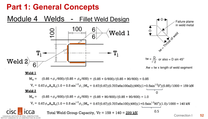
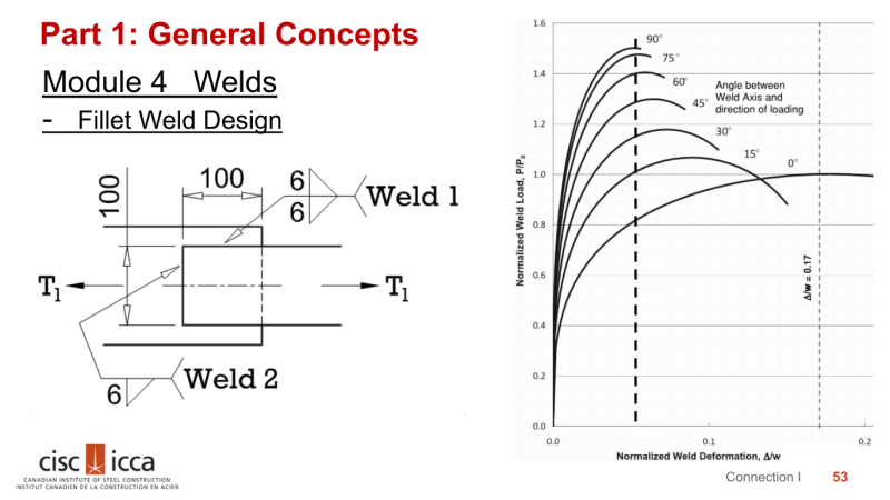
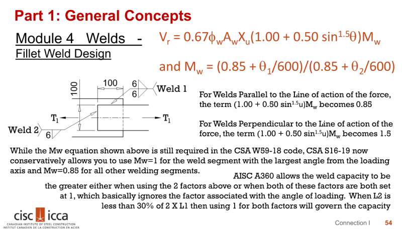
Here are some good summary slides of the concept:
Module4_52_fwrmhw.png
Module4_53_tfvekj.png
Module4_54_fr4mxn.png


You can read the research work here or pay for it here.
 
skeletron said:
Here are some good summary slides of the concept:

This doesn't really answer the question.

Given that the extreme fiber weld is normal to the force, I'm thinking my Mw will be 1.0 since theta1 and theta2 are 90°, and that is my highest stressed weld.
 
EngDM said:
skeletron said:
Here are some good summary slides of the concept:
This doesn't really answer the question.

Given that the extreme fiber weld is normal to the force, I'm thinking my Mw will be 1.0 since theta1 and theta2 are 90°, and that is my highest stressed weld.

Sorry. The lack of question mark in your post made me think that your query was more about understanding Mw. I now see your question as:

EngDM said:
...wondering what your thoughts are on the application of Mw for all around (circular welds)...

I get what you are debating on a theoretical level, but that would require summing individual segments of the weld at various angles. For an everyday application, I would analyze at the 0 degree level and likely focus on providing a weld that develops the section.
 
skeletron said:
I get what you are debating on a theoretical level, but that would require summing individual segments of the weld at various angles. For an everyday application, I would analyze at the 0 degree level and likely focus on providing a weld that develops the section.

Would you agree with the following: Calculate the force in the weld on a kN/mm basis using the section modulus method or the elastic method, and compare this value to the calculated weld strength (at zero degrees conservatively_ with Mw = 1.0 since the critical weld (for bending) is normal to the applied force? My thought is, taking the zero degree strength would already be conservative, and when you get to the welds that are actually zero degrees, the stress would decrease by then anyways.

Basically, don't rely on the extra strength for 90°, but also don't cut the capacity down by another 15% for multi-orientation since in reality the Mw would vary per infenitesmal length along my weld curve (since it's a circular weld).

When doing rectangular welds it's much more cut and dry.
 
I would modify your theoretical proposal of using the elastic method and use partial length on each side. Say, 25% of the circumference as a line segment on each side. Of course, if this is a 3" or 4" round I would save brain cells and look more at getting the weld to develop the strength of the tube. If it is a 8" or 12"+ round with forces to match, then maybe I would consider going at it on a theoretical level.

EDIT: I think the flaw in going too deep into this is that the strain compatibility of the weld is not even discussed. In my understanding, that is the reasoning behind the introduction of Mw. Any simplification of the weld length as a line is just a brute force method to hop over the hurdle that is strain compatibility.
 
skeletron said:
I would modify your theoretical proposal of using the elastic method and use partial length on each side. Say, 25% of the circumference as a line segment on each side. Of course, if this is a 3" or 4" round I would save brain cells and look more at getting the weld to develop the strength of the tube. If it is a 8" or 12"+ round with forces to match, then maybe I would consider going at it on a theoretical level.

Right, this is for a guardrail application around an RTU, and we all know that it's probably fine with minimal welding but I'm delving into making it code compliant and not just "it's how it's always done". So I'm working with like 1.9"Ø tubes. So you're suggesting to just develop the full strength of the tube instead of looking into the forces on it? So use my Mf and Vf as the Mr and Vr of the tube?
 
EngDM said:
So you're suggesting to just develop the full strength of the tube instead of looking into the forces on it? So use my Mf and Vf as the Mr and Vr of the tube?

In this case yes. It appears you are using either a Sch40 or Sch80 pipe, the wall thickness is pretty thin. The weld is going to be whatever 1-pass weld they can apply. The Mf and Mr are pretty close from my quick glance at the numbers.
 
Status
Not open for further replies.

Part and Inventory Search

Sponsor