Continue to Site

Eng-Tips is the largest engineering community on the Internet

Intelligent Work Forums for Engineering Professionals

  • Congratulations KootK on being selected by the Eng-Tips community for having the most helpful posts in the forums last week. Way to Go!

Allowable loads on nozzles for pressure vessel 1

Status
Not open for further replies.

HOUARI YAHIAOUI

Petroleum
Dec 13, 2017
29
Hello experts
my question is about allowable loads on nozzles for pressure vessel.
the standard of the company wich I work at, has tabular alloawble values of forces (Fa,Fc,Fl) and moments (Mt,Mc,and Ml) according to flange rating.
The problem is when I choose to analyse loading for nozzles using Pv elite with the WRC 107 code, I found that there is three categories for loads on nozzles :
1.Substained
2.Expansion
3.Occasional

In our standard there is no mention of the category of the tabular loads. hence I guess that the tabular loads are substained loads normally, so what about the two other categories, how do I to obtain the limit values for forces (Fa,Fc,Fl) and moments (Mt,Mc,and Ml) to enter in pv ellite in order to analyse loads?
 
Replies continue below

Recommended for you

1. Ask the standard owner.
2. Get actual loads from your piping analyses.
3. If you only have a single set of forces & moments, the most conservative approach I think would be to apply them in the sustained case at 1x intensity and in the expansion case at -2x intensity. E.g. Fa +1000 in sustained and -2000 in expansion. This would give an operating case (SUS+EXP) of -1000. Piping engineers, myself included, aim to keep their operating case loads within the limits of the allowable loads but don't necessarily care if they go from -99.9% to +99.9%. Often the allowable loads given by pressure vessel vendors are ludicrously low.
4. If you are evaluating flange ratings rather than local stresses, all bets are off. See BPV VIII-1-16-85.

 
A couple of additional comments and disagreements with ConstantEffort.

I agree that the owner of the specification is the one who should be consulted in this manner. I also agree that actual loads, those calculated including the effects of nozzle flexibility, should be used.

It is my opinion that, though, most software that makes use of WRC 107 to calculate the stresses in the vessel shell due to nozzle loads, incorrectly categorize the stresses from the various piping load cases. Table 5.6 in VIII-2 is quite clear that regardless of the source of the piping loads (self-weight or restrained free thermal expansion), the membrane stresses are to be categorized as primary. However, the mistake that is made is that the membrane stresses caused by restrained free thermal expansion of the attached piping (what the piping engineers will refer to as Expansion forces/moments) are categorized as secondary. This is fundamentally incorrect and potentially massively unconservative.

Therefore, I recommend that you place all loads into the Sustained bin.

With respect to evaluating flanges due to nozzle loads, please be aware of Code Case 2901. And evaluating flanges is not a matter of if you do it, but when. As was pointed out in the Interpretation, such checks are indeed mandatory.
 
TGS4 said:
most software that makes use of WRC 107 to calculate the stresses in the vessel shell due to nozzle loads, incorrectly categorize the stresses from the various piping load cases.

Interesting! I hadn't heard this opinion before and I don't often work in Div 2, so I had not seen the table you mention.

PRG's FE107 appears to use this incorrect approach if I understand your point correctly. I just ran a test case to verify with no weight or pressure loads, only operating loads. Stresses "PL" are 0 while "PL+Pb+Q" are non-zero and compared against S_PS.

Without being an expert myself, I have taken PRG's and Tony Paulin's opinion as being state of the art. Hopefully I am just misinterpreting either your statement or FE107's results. Where have I gone wrong?

 
It's not just the PRG version that does it wrong. Most software that I'm aware of does it wrong. We changed the rules with the 2007 Edition, but most software pre-dates that, and so was just never updated. Not casting aspersions on any software, but it needs to be understood how the Code requires certain stress categorizations. If you're using WRC 107, then you need to be more than familiar with how VIII-2 works. In the end, it's not a software fault, but an engineer issue.
 
TGS4

Should we place occasional nozzle loads in the Sustained bin? That is add all the loads, gravity/pressure, thermal pipe expansion and say (0.7)EQ loads together and run just the one Sustained load case? Seems to me that table 5.3 says no thermal (T) load required with EQ. but table 5.1 includes 'thermal loads' under 'normal + occasional.'

Are there two types of thermal loads. Table 5.1 (5) Thermal loads and Table 5.2 'T' Self-restraining thermal loads?

For others reading this thread Table 5.6 says

pic1_gj0r6q.png


Thanks
 
Thermal piping loads and thermal vessel loads are different things. It comes down to the magnitude of the resulting displacement. If you are using elastic stress analysis, then you should be placing piping thermal loads as if they were the same as piping dead loads.

I would treat piping occasional loads from whence they came (wind or seismic).
 
In Table 5.6 where Nozzle/Nozzle Wall/Differential Expansion/Membrane Stress = Q (Secondary).
Does this only apply to local stresses caused by local transient thermal gradients?
I assume as suggested by TGS4, that it doesn't apply to stresses caused by displacement due to thermal expansion of pipework located a few meters away form the stressed location.
 
DriveMeNuts - your assumption is correct to my understanding.
 
Hello an thank you for evryone for your response;
Our specification said that the tabular loads shall be considered as being caused by 66% thermal and 34% dead weight loads, IN Excel sheet of loads on nozzles the loads are sustained, occasional and expansion load, so my understanding is:
1) for expansion loads : the factor of multiplication is 0.66 so the tabular loads shall be multiplier by 0.66.
2) for sustained loads : the factor of multiplication is 0.34 so the tabular loads shall be multiplier by 0.34.
3) for occasional loads : not considered so the factor is 0.
Is my understanding is correct?
 
Were you paying attention to what I said about assigning everything to "sustained", because the stresses caused by expansion loads are incorrectly considered by most software?
 
TGS4

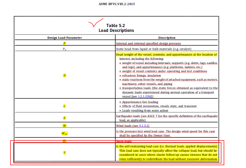
In table 5.2 of SEC.8-div2-part5(2015), there is a description for "T" :
"This load case does not typically affect the collapse load, but should be considered in cases where elastic follow-up causes stresses that do not relax sufficiently ...."

I think it means that if piping expansion loads(applied displacement)are strain limiting(there is not elastic follow-up condition) then they will go down after deformation.
Therefore if this is the case, the piping loads are secondary type and they should not be included in collapse evaluating.

What do you think about this?
 
How they describe it in PVElite:
[ul]
[li]Sustained - (SUS) Primary loads, typically weight + pressure + forces.[/li]
[li]Expansion - (EXP) Secondary thermal expansion loads.[/li]
[li]Occasional - (OCC) Irregularly occurring loads such as wind loads, seismic loads, and water hammer.[/li]
[/ul]
PVElite then performs WRC 107/537 for each set of loads individually then combine them as appropriate with acceptance criteria below:
[ul]Sustained Loads:
[li]Pm <= Sa[/li]
[li]Pm+Pl <= 1.5Sa[/li]
[/ul]
[ul]Sustained + Occassional Loads:
[li]Pm <= 1.2*Sa[/li]
[li]Pm+Pl <= 1.2*1.5Sa[/li]
[/ul]
[ul]Sustained + Occassional + Expansion Loads:
[li]Pm+Pl+Q* <= 3*Sa[/li]
* Expansion Loads are considered as Q by PVElite
[/ul]

That is how PVElite performs their calculation.
However, our practice is to consider the 'design nozzle force/moments' (in the project specification) as sustained even though it is actually sustained+occasional+expansion since there is no breakdown of the loads on several different cases at the beginning stages of the project, and it would be time consuming.

Applying a multiplier of 1.2 though to "1.5*Sa" for Pm+Pl is however a long question of mine why PVElite evaluates it like that. Is that acceptable for ASME VIII, Div.2?

For cases where Sa/Sy doesn't exceed 0.55 (e.g. SA-516 70, SA-387 11 Cl2), Pm+Pl wouldn't exceed Sy.
For the case of SA-240 304L, 1.2*1.5*Sa would exceed Sy and PVElite evaluates it that way.
 
RaymondN- there's so much that's wrong with what you wrote (what some software is doing) that I literally don't know where to begin.

Milad.Hmk, T is for the stresses in situations like the differential thermal expansion between cladding and base metal. Restrained free thermal expansion of attached piping is not T. Elastic follow-up is always a concern. I wrote two papers on this topic:


TGS4, if you're referring to the acceptance criteria, that is how PVElite evaluates it. I will paste a portion of the calculation when I get a chance, but it is basically:
Code:
[ul]
[li]SUS           Pm         < Sa[/li]
[li]SUS+OCC       Pm         < 1.2*Sa[/li]
[li]SUS           Pm+Pl      < 1.5*Sa[/li]
[li]SUS+OCC       Pm+Pl      < 1.2*1.5*Sa[/li]
[li]SUS+OCC+EXP   Pm+Pl+Q    < 3*Sa[/li][/s]
[/ul]
I'd like to know your opinion about that, which was my last 2 paragraphs were about. Compress software doesn't categorize between sustained, occasional, and expansion on nozzle loads so I can't compare.
 
I don't use PVElite, so I can't comment on the specifics. But that is completely not compliant with the current ASME Section VIII-2, Part 5. One could argue fast it complied with the pre-2007 Code, but realistically, that was 12 years ago. And the Code went through a complete rewrite in the interim.
 
TGS4, thanks for your confirmation. PVElite still does that calculation in their 2017 edition (ASME 2015 Ed). I'm not sure with their 2018 version if it's the same. Just to add, below is a sample WRC107 stress summation by PVElite.

SA-240 304L at 70°F, Sy should be at 25 ksi.

Code:
   WRC 107/537 Stress Summations:
                                                                                                       
   Vessel Stress Summation at Attachment Junction (psi)
                                                                                                       
                  |                    Stress Intensity Values at                                 |
   Type of        |                                                                               |
   Stress    Load |       Au        Al        Bu        Bl        Cu        Cl        Du        Dl|
   ------------------------------------------------------------------------------------------------
   Circ. Pm (SUS) |     6979|     7279|     6979|     7279|     6979|     7279|     6979|     7279|
   Circ. Pm (OCC) |        0|        0|        0|        0|        0|        0|        0|        0|
   Circ. Pm(TOTAL)|     6979|     7279|     6979|     7279|     6979|     7279|     6979|     7279|
   Circ. Pl (SUS) |      -63|      -63|       48|       48|      -15|      -15|        4|        4|
   Circ. Pl (OCC) |      -21|      -21|        6|        6|      -10|      -10|        0|        0|
   Circ. Pl(TOTAL)|      -85|      -85|       55|       55|      -25|      -25|        3|        3|
   Circ. Q  (SUS) |     -117|      117|       86|      -86|     -155|      155|      106|     -106|
   [COLOR=#EF2929]Circ. Q  (EXP) |      -62|       19|       16|       -3|     -100|       79|       40|      -41|[/color]
   Circ. Q  (OCC) |      -40|       40|       10|      -10|      -89|       89|       41|      -41|
   Circ. Q (TOTAL)|     -220|      177|      113|     -100|     -345|      325|      188|     -189|
   ------------------------------------------------------------------------------------------------
   Long. Pm (SUS) |     3489|     3489|     3489|     3489|     3489|     3489|     3489|     3489|
   Long. Pm (OCC) |        0|        0|        0|        0|        0|        0|        0|        0|
   Long. Pm(TOTAL)|     3489|     3489|     3489|     3489|     3489|     3489|     3489|     3489|
   Long. Pl (SUS) |      -23|      -23|       12|       12|      -23|      -23|        8|        8|
   Long. Pl (OCC) |      -10|      -10|        0|        0|      -15|      -15|        0|        0|
   Long. Pl(TOTAL)|      -33|      -33|       11|       11|      -38|      -38|        8|        8|
   Long. Q  (SUS) |     -191|      191|      140|     -140|      -81|       81|       50|      -50|
   [COLOR=#EF2929]Long. Q  (EXP) |      -77|       56|       14|      -16|      -63|       33|       17|      -17|[/color]
   Long. Q  (OCC) |      -67|       67|       15|      -15|      -48|       48|       17|      -17|
   Long. Q (TOTAL)|     -335|      315|      170|     -172|     -193|      163|       86|      -85|
   ------------------------------------------------------------------------------------------------
   Shear Pm (SUS) |        0|        0|        0|        0|        0|        0|        0|        0|
   Shear Pm (OCC) |        0|        0|        0|        0|        0|        0|        0|        0|
   Shear Pm(TOTAL)|        0|        0|        0|        0|        0|        0|        0|        0|
   Shear Pl (SUS) |        5|        5|       -5|       -5|        0|        0|        0|        0|
   Shear Pl (OCC) |        2|        2|       -2|       -2|       -2|       -2|        2|        2|
   Shear Pl(TOTAL)|        8|        8|       -8|       -8|       -2|       -2|        2|        2|
   Shear Q  (SUS) |        0|        0|        0|        0|        0|        0|        0|        0|
   [COLOR=#EF2929]Shear Q  (EXP) |        2|        2|       -2|       -2|        0|        0|        0|        0|[/color]
   Shear Q  (OCC) |        0|        0|        0|        0|        0|        0|        0|        0|
   Shear Q (TOTAL)|        2|        2|       -2|       -2|        0|        0|        0|        0|
   Pm (SUS)       |     6979|     7279|     6979|     7279|     6979|     7279|     6979|     7279|
   ------------------------------------------------------------------------------------------------
   Pm (SUS+OCC)   |     6979|     7279|     6979|     7279|     6979|     7279|     6979|     7279|
   ------------------------------------------------------------------------------------------------
   Pm+Pl (SUS)    |     6915|     7215|     7027|     7327|     6963|     7263|     6983|     7283|
   ------------------------------------------------------------------------------------------------
   Pm+Pl (SUS+OCC)|     6894|     7194|     7034|     7334|     6953|     7253|     6982|     7282|
   ------------------------------------------------------------------------------------------------
   Pm+Pl+Q (Total)|     6673|     7371|     7147|     7233|     6607|     7578|     7170|     7092|
                                                                                                       
                                                                                                       
   Stress Summation Comparison (psi):
                                                                                                       
   Type of        |     Max. S.I.     S.I. Allowable     |      Result     |
   Stress Int.    |                                      |                 |
   -------------------------------------------------------------------------
   Pm (SUS)       |          7279             16700      |      Passed     | [COLOR=#EF2929]<- SA-240 304L Allowable at 70°F[/color]
   [COLOR=#EF2929][b]Pm (SUS+OCC)   |          7279             20040      |      Passed     | <- 1.2*16.7 ksi[/b][/color]
   Pm+Pl (SUS)    |          7327             25050      |      Passed     | [COLOR=#EF2929]<- 1.5*Sa[/color]
   [COLOR=#EF2929][b]Pm+Pl (SUS+OCC)|          7334             30060      |      Passed     | <- 1.2*1.5*16.7 ksi[/b][/color]
   Pm+Pl+Q (TOTAL)|          7578             50100      |      Passed     | [COLOR=#EF2929]<- 3.0*Sa[/color]

So in response to OP, using Occasional and Expansion input in PVElite wouldn't be compliant to ASME VIII-2, Part 5.
 
If it makes you feel better, I think that the vast majority of WRC 107 implementations get it wrong.
 
TGS4
I do not agree with you.
You can see the definition of "T" in table 5.2 of ASME SEC.8-2 PART 5
So piping loads(applied displacement) could be in category of load case "T"
Untitled_q0s3cx.png
 
Read my papers to see my justification. Piping restrained free thermal expansion is often not T. See also Table 5.6.

In most situations, it's a matter of engineering judgement, not a right/wrong situation.
 
Status
Not open for further replies.

Part and Inventory Search

Sponsor