Continue to Site

Eng-Tips is the largest engineering community on the Internet

Intelligent Work Forums for Engineering Professionals

  • Congratulations KootK on being selected by the Eng-Tips community for having the most helpful posts in the forums last week. Way to Go!

Aluminium Design:- How to calculate αc (alpha c) in table 8.2, BS-EN-1999-1-1-2023

Joesman

Structural
Nov 28, 2024
4
Hi I'm trying to determine the classification of a Class1 or Class 2 section using the aluminium design codes BS-EN-1999-1-1-2023. To do this I'm directed to table 8.2 which uses αc in each of the formulae, but I cant see anywhere that clearly confirms how to calculate αc. Hopefully someone on this forum has got this sussed and can help. Kind regards.
 
Replies continue below

Recommended for you

I believe you calculate alpha from the actual stress distribution in the member cross section. So under axial and bending you need to calculate the point at which the stress changes from tension to compression. This gives you alpha. It is the same in EC3.
 
I believe you calculate alpha from the actual stress distribution in the member cross section. So under axial and bending you need to calculate the point at which the stress changes from tension to compression. This gives you alpha. It is the same in EC3.
Thanks for your response Ussuri. I assume you mean that alpha c is the the distance from the outer fibers of the shape to the neutral axis depending on which direction the loading is applied to the member. Distance to neutral axis from the outermost fibers, is this the same as alpha c?
 
Thanks for your response Ussuri. I assume you mean that alpha c is the the distance from the outer fibers of the shape to the neutral axis depending on which direction the loading is applied to the member. Distance to neutral axis from the outermost fibers, is this the same as alpha c?
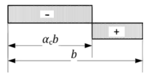
The diagram in table 8.2 shows that ac
 
1733148136843.png
The diagram in table 8.2 indicates the distance from the outer most fibers from the compression zone to the neutral axis should always be used. I'm using a c-section which is not symmetrical so it will be a significant difference to the distance to the neutral axis from both directions in this case. If i apply a positive load up the way to a c-section with the flange up and toes down then i'm assuming I should used the depth from the outer fibers of the toes to the neutral axis as the toes will go into compression in the loading arrangement which is indicated in the negative zone in the image above.
 

Part and Inventory Search

Sponsor