Continue to Site

Eng-Tips is the largest engineering community on the Internet

Intelligent Work Forums for Engineering Professionals

  • Congratulations SSS148 on being selected by the Eng-Tips community for having the most helpful posts in the forums last week. Way to Go!

Aluminum Louver Blade Design

Status
Not open for further replies.

KootK

Structural
Oct 16, 2001
18,563
Disclaimer: this is a lazy man's post. I am indeed asking responders to do research that I could surely do myself given enough time and fee (I long ago ran out of both).

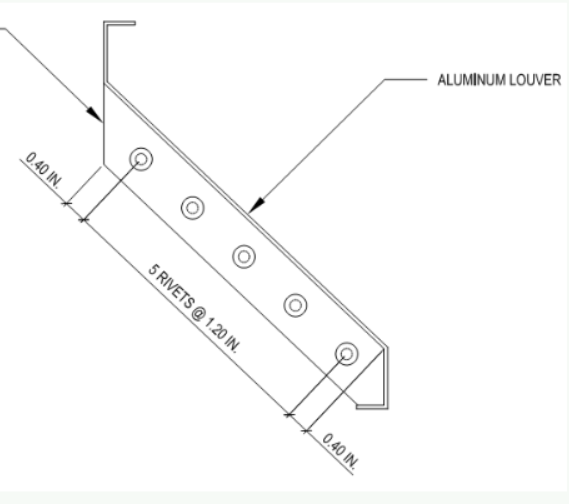
I need to design the aluminum thing shown below for wind and guardrail-ish loads (related to another recent thread of mine). Biaxial flexure on an unbraced z-ish section. A common configuration is coming up failing badly (even just wind), I've got twenty pages of near meaningless aluminum calcs that read like Egyptian hieroglyph, and I've been rotating axes like I was back in second year college. I just feels as though it should not be this hard.

So, my desperate questions are:

1) Wind. Folks seem to agree on treating the thing as solid. However, with that decision taken, do you then apply that same horizontal wind load to the blade as a 45 degree load? Wind does only act perpendicularly to surfaces after all. It makes a big difference as 25 psf "wall" load then becomes 25 PSF weak-ish axis load.

2) Is there any better design resource to be using other than the Aluminum Association's Aluminum Design Manual. I'd sacrifice a thumb for a damn table of flexural capacities.

3) As much as it shames me to ask this, anybody got a worked example that they could point me to?

Capture_01_bmrxgt.png


I like to debate structural engineering theory -- a lot. If I challenge you on something, know that I'm doing so because I respect your opinion enough to either change it or adopt it.
 
Replies continue below

Recommended for you

Tried to design a similar thing once. There were a lot of them. The builder agreed to fabricate a few, and we load tested them.
 
KootK:
You said...., “As much as it shames me to ask this, anybody got a worked example that they could point me to?” You do understand that plagiarism is frowned up, right? Although, I’m sure that you got the second part of that sentence (meant to put quotes around it) directly from one of the hundreds of OP’s that you have been so kind as to answer in such great detail, good advice, good sketches, links and all. So...., o.k. :)

No exact solutions or worked examples, but again, just some food for thought.
FEA should be your friend on this one, and you know that far better than I do. I suspect the gage of the louver material is heavier than we would normal think, vibration, bending strength, etc. all being accounted for and considered. I suspect that most of these are grand fathered, as adequate for purpose, since they’ve been around for so long. And, that history has shown them to work, with occasional vibration/flutter adjustments being needed. I also bet that they would not check out if you applied today’s IBC, wind loads, LRFD and all that new crap. Rather, the manuf’er. has a long design history, testing for strength and air flow, etc, and is self insured if they have to do some fixin, every so often. You may not have that advantage. It seem to me that on some large louvered openings/frames, I’ve seen vert. lines of stiffeners btwn. the horiz. louvers, in effect, making them stiffer and also act in unison. These would be Z or C shapes in cross section and parallelograms in elevation (side view), with height equal to the louver spacing and width equal to the louver section front to back dim. And, I think I have also seen some light structural vert. framing elements behind the actual louvered frame in the interior. I think Hokie’s testing idea is a pretty good one, particularly when you are kinda starting from scratch.
 
CUFSM may be of help, and the price is right.


Mike Halloran
Pembroke Pines, FL, USA
 
I do a fair amount of aluminum design.

As others have suggested, testing is the route to go on these custom shapes if you want to get any allowable loads through them. Your calcs will not be your friend.

If I were going to design this, I would break the applied loading down into loads applied parallel and perpendicular to the principle axes of the shape.
To find the principle axes of the shape you can use any program of your liking (I like to use autocad or a program called shape builder if you have it)

From there, I would calc bending moments about the principle axes, and then calcing bending stresses from M/S (where S is the section modulus of the principle axes) and then compare to the all of the applicable aluminum design codes allowables for flexure. If you have the program shape builder, you are sitting easy and it auto generates the stresses due to moments you specify about the principle axes.

Shear stresses are little more complicated but I typically just do an average stress over the entire cross section (typically shear is not controlling on these).

One other note, I ofter find that thermal loading seems to be the controlling case in a lot of the exterior aluminum items. Check to see what you need to design for, but typically its around 120 deg F. If you do not detail for some sort of slip to thermal expansion/contraction, the hand calcd axial load can quickly get out of hand even on a short element.

S&T

 
It looks pretty stout - just run with it :>
 
if you want strength properties for Al try AR MMPDS-01 or Mil Handbook 5 (both on everyspecdotcom)

another day in paradise, or is paradise one day closer ?
 
Mike:
CUFSM should be right up the alley... an ideal application, a very powerful concept and relatively easy to use. Design loading may be an issue. May be time consuming (no budget).

Dik
 
KootK,
Have you tried contacting a louver manufactures (such as Construction Specialties) to see if they have something that meets the project requirements? It seems like it would be more cost effective than reinventing the wheel
 
Figure out section properties on principal axis with autocad

apply load horizontally break it into components across principal axis.

The issue will be deflection across the weak axis - l/120 is the usual standard

a shape like that in .080 material in 5052 H32 should go about 4 ft or a bit more at 25 PSF

The AIR Movement and Control association has a design guide (may still be in draft form) that shows how to do this - you can contact them

Bill Vincent
Lite Metal Design


Your Question

#1) if there are multiple blades spaced "close" together, then i would take that perpendicular solid 'wall' wind force and have it act along the weak axis only for the exposed portion. in other words, say you have these at 4" o.c. then only 3" is exposed, you get 25psf*0.25ft = 6.25plf on the exposed portion only.

To me, the wind can be hitting the louver at an angle (say 45 upward) and therefore hitting the wall at 45 degrees but the fin at 90 degrees.

#2) Only one i know of... you can always use steel with lower allowable stresses than after final design recheck per Aluminium (because that sounds efficient!)

#3) sorry... pre-engineered guys have stuff for their purlins/girts... but steel and primary axis.
 
Status
Not open for further replies.

Part and Inventory Search

Sponsor