Continue to Site

Eng-Tips is the largest engineering community on the Internet

Intelligent Work Forums for Engineering Professionals

  • Congratulations GregLocock on being selected by the Eng-Tips community for having the most helpful posts in the forums last week. Way to Go!

An unusual retaining wall application - I think

Status
Not open for further replies.

Eng_1234

Mechanical
Nov 12, 2019
3
I have a need to pull something very heavy along the ground, where the calculated pull is in the order of hundreds of metric tonnes force. The pull will be done by a large winch, with a big wire, all straightforward so far. The question I have is how to anchor the winch (i.e. react the force of the pull).
It's temporary so I don't want to design a concrete foundation, the plan is to use a ground anchor to tie back to, as follows.

A sheet pile wall driven into the sandy (ish) ground and a series of anchor wires from the "wall" to the winch.

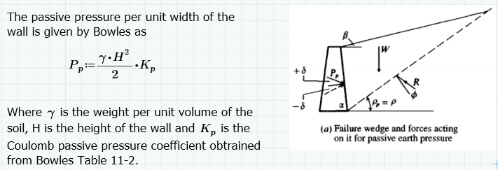
I have assumed a simple retaining wall load case and Coulomb Earth Pressure Theory but rather than the conventional "active" pressure case of the wall resisting the mass of soil behind it, I am assuming the "passive case" as if the wall were trying to push the soil back. Has anyone used this before and does it sound a reasonable approach?

I have made some assumptions for ground mass and slip angle, trying to be conservative for both, but if there happens to be a water table at the depth of the wall (likely) I can't make up my mind whether the water will act to increase the holding power of the "anchor" or act against me. Or since the water would be on both sides of the "wall" is it effectively balanced?
I have assumed a value for saturated soil.

 
Replies continue below

Recommended for you

"pull something heavy"....hardly sufficient detail. Which does make it sound like a homework problem.

We need the dimensions of the something heavy, the pull length, geometry of the problem (i.e. all flat ground?), location of project, ground conditions (sandyish, is hardly enough info).

Explain what you man by ground mass and slip angle?

One comment, water will reduce your effective stress which will reduce you sliding resistance, depending where its location.

In summary, more details = better answers
 
Homework? Oh dear me, if only I had so much to look forward to.

The details of the something heavy and the rest of the operation I'm comfortable with and won't be shared on a public forum for all the usual reasons. Sorry. The question I asked resolves to the geotechnical details of an anchor in earth to resist a large horizontal (or nearly horizontal) pull.

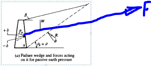
Hopefully the sketch below helps illustrate the normal retaining wall technique, although in my case the wall in the sketch will be driven into place, with earth on both sides.

Capture_gnp1dw.png
 
Eng 1234 said:
Has anyone used this before and does it sound a reasonable approach?

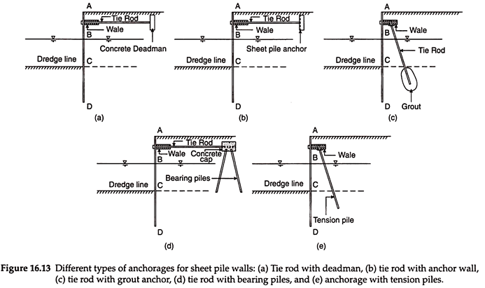
Various anchorages for sheet pile walls. For your high, dynamic point load application, a concrete "deadman" sounds preferable, IMHO. Don't want a jury rigged sheet pile wall to shift under load. Removal of the temporary concrete will add to project cost... sometimes that is money well spent.

clip_image018-14_zvt0if.png


[idea]
 
Sounds like a job for pair, or a couple of pairs, of driven H-piles, with a rigid frame or concrete cap (configuration "c" in the figure posted by SRE). That's assuming the foundation material isn't too hard to drive them. If you have really hard material near the surface, consider grouted rock anchors.

Rod Smith, P.E., The artist formerly known as HotRod10
 
This question isn't about retaining walls or conventional soil anchors (in the slope stabilisation sense). For the avoidance of doubt the force I would like to resist is in the direction indicated in the sketch below.

Capture_hwqqf3.png


i.e. all the tension tie rods and piles in figure 16.13 above would be in compression.

A block anchor (deadman) may well end up being the end solution although the calculation of the size and how to treat the effect of water likely remains the same.
 
In your sketch, the winch is to the right of the wall. The winch cannot be buried in the ground. Therefore, depending on the geometry, there could be a reduction in the available passive resistance of the wall if you cannot develop the full passive wedge. Make sure the excavated or non-filled area where the winch is sitting will allow sufficient passive resistance with an acceptable safety factor. Also, make sure that the wall is designed so that it can retain the soil before the winch pulls on the wall. The wall needs to be stable without any assistance from the winch.

 
If the wall (piles, deadman, whatever) is buried in the soil and will be needing the earth to resist the applied load, then yes you will be relying on passive pressure.

The resultant of the earth pressure will be someplace between half of the element height and the lowermost 1/3rd of the element height, where height is defined as "the buried portion".

Use the Rankine formula (simpler than Coulomb) for passive pressure - Coulomb is unconservative for passive pressure as soil friction angle increases.

If you are using discrete elements (soldier piles), you will want to look at the work of Broms and Wang-Reese on the passive resistance of discrete piles.
 
How about simply use stacked concrete or steel planks slabs as counter weight to resist the pull force? Steel is preferred, because it is salvageable and reusable.
 
stack your concrete 50 ft wide by 50 ft long by 10 feet high and you should be good
 
For holiday's fun, let's consider the following 3 scenarios in developing required resistance to the pull force.

Assumptions:
Unit Weight of Concrete, 150 lb/cf
Unit Weight of steel, 490 lb/cf
Unit Weight of Soil, 125 lb/cf
Concrete-Soil Friction Coefficient, 0.5
Steel-Soil Friction Coefficient, 0.3
Passive Lateral Earth Pressure Coefficient, 3

1) 10'x10'x10' Concrete Block, R = 10x10x10x0.15x0.5 = 75 kips
2) 10'x10'x10' Steel Stock, R = 10x10x10x0.49x0.3 = 147 kips
3) 10'(b)x10(h) Earth Retaining Structure, R = 0.5x(0.125)(10^2)x10x3 = 187.5 kips

Other than pull force consideration, availability of material, material transportation, cost of installation/demolition/disposal are factors to be considered in the selection process too. I personally prefer the steel, as it has the advantages stated before.
 
As you can see from retired13's examples, developing several hundred tonnes of resistance takes a big structure. If the soil has high cohesion, the passive resistance of the wall per linear foot is 2*C*H +Gamma*H^2*Kp/2. C = cohesion in tonnes per square foot; 3 would be a big number. Gamma is roughly 0.06 tonnes per cubic foot. Kp could be as small as 1.0 for cohesive soil. H is the wall height in feet. If the soil is cohesionless sand, C is zero and Kp is somewhere between 3 and 5.

If the soil can be penetrated by helical anchors, you might consider a field of such anchors installed at an angle between 30 and 45 degrees from horizontal, linked up by cables to a common connection. Lay a railroad tie or two or three under each cable to take the vertical component. You may be able to rent the anchors; they can be recovered. You still need a geotech to run the calculations.

Yes, passive resistance of a sheet pile wall is a reasonable approach. You could tie your cables near the lower third point or tie the top of the wall to a second wall some distance behind the first.

Ground water will buoy up the soil and reduce the passive resistance.
 
Anybody studied how the old Egyptian built the pyramid? Can be a good holiday assignment :)
 
Yeah, you could get it onto timber rollers, like the Egyptians used for the pyramid blocks.

Rod Smith, P.E., The artist formerly known as HotRod10
 
jdonville,

Thanks for the link. Gee, too expensive for a retiree :)

As an engineer, we tend to be overthinking at times, Sometimes simple is the beauty.
 
In one of the pumped-storage project (a hydroelectric power generation station), permanent stainless steel plates were placed under the transformers to reduce the friction to allow for ease in pull/push required during maintenance. I don't recall the weight of the transformer, only remember that it was trucked to the project site as individual modular and field assembled. Each module required road permit alone the route, and the complete unit was too heavy to be handled by crane.
 
Have you considered using screw anchors? Cheap to install and they could be unscrewed at the end of the project. Depending on the load and the size of the anchors, it may take several anchors fanned out.
 
1 tonne force = 2200 pounds. "Hundreds of tonnes" should be too much for screw anchors to resist. For example, 200 tonnes = 441 kips. That's a LOT of helical "screw anchors."

 
Status
Not open for further replies.

Part and Inventory Search

Sponsor