Continue to Site

Eng-Tips is the largest engineering community on the Internet

Intelligent Work Forums for Engineering Professionals

  • Congratulations IFRs on being selected by the Eng-Tips community for having the most helpful posts in the forums last week. Way to Go!

Anchor Bolt Shear Reinforcing Stirrup Development 5

Status
Not open for further replies.

waytsh

Structural
Jun 10, 2004
373
Detail below is drawn to scale but I can provide specific dimensions if needed. My question is, would you consider the top stirrup in this condition adequately developed to provide shear reinforcing for the loading condition shown? Anchors fail without some form of shear reinforcing. Thank you!

Pedestal_Layout_rfyces.png
 
Replies continue below

Recommended for you

It's not the most ideal scenario. Is there anything in the way of moving the anchor to the right? Is this a anchor bolt scenario and then covered by a tube steel post over the 4 anchor rods? That said, you could consider at least the first stirrup to be developed. PCI did research on stirrups in thin toppings.
 
I would use a Strut-and-Tie model, Widianto et. al (CSA Today, Vol. III, No. 12) is a common reference for these situations.


This is common is industrial design. Try googling Design of Anchor Reinforcement in Concrete Pedestals or PIP STE05121 Anchor Bolt Design Guide or Design of Headed Anchor Bolts
image_zl1ffy.png
 
Anchor bolt for petrochemical facilities is also a good reference


Capture_wvq5vb.jpg
 
I think that you're good if you consider your shear load delivered to your rear anchors, as your sketch would imply. In that case, I'd just lean on the provision that allows beam stirrups to be considered instantaneously developed when #5 or less and hooked around a longitudinal bar. Granted, your claim to the longitudinal bar is a bit dubious in this scenario for the uppermost stirrup.

If you don't have weld washers on the other hand, then I think that your shear needs to be assigned to the front anchors. Then none of this stuff will save you.
 
bones206 said:
You can also conservatively calculate the pullout capacity of the hooked leg of the tie as a J-bolt anchor.

Can you elaborate on that a bit? What I'm imagining sounds like a J-bolt with near zero embedment which would be sketchy.
 
On a pedestal with small plan dimensions, the hooked leg of the tie might not be long enough to be considered fully developed for Fy, so I may assign it a lower pullout capacity instead. So in the OP's example I would take this approach with the circled leg of the tie.

Pedestal_Layout_rfyces_i0v7wp.png
 
Thank you for the all the responses. This is all very helpful.

KootK said:
If you don't have weld washers on the other hand, then I think that your shear needs to be assigned to the front anchors. Then none of this stuff will save you.

Yes, I am calling out weld washers. Otherwise as you alluded I wouldn't have a prayer of making this work.

bones206 said:
On a pedestal with small plan dimensions, the hooked leg of the tie might not be long enough to be considered fully developed for Fy

Good point. According to my layout the hook is a little over 8" past the failure plane.
 
I'll sometimes try to dictate location of the tie hooks in the pier detail. Or if the loads can reverse, I'll call out alternating hook locations in each layer of ties. But the chances of this actually happening when they assemble the pier cage is slim to none.
 
The fitment that is hooked around the vertical bar would develop its strength basically immediately beyond the hook. The codes imply that this is the case for small diameter fitments that are hooked around a transverse bar of the same or greater diameter. I believe KootK mentioned this already.

As for alternating the hook position, I have never seen a need to do this. As long as the hooks turn inwards and are anchored in the core, these bars are considered to be fully anchored.

My only concern, if I am ever relying on a bar developing its strength immediately at the hook, is whether the cage is assembled so that the hook and transverse bar are in intimate contact to begin with, which is rarely the case. There is one particular study that showed that the hook alone, without the presence of an anchoring bar in the corner, can be enough to develop the full strength of a small diameter bar.
 
bones206 said:
On a pedestal with small plan dimensions, the hooked leg of the tie might not be long enough to be considered fully developed for Fy, so I may assign it a lower pullout capacity instead. So in the OP's example I would take this approach with the circled leg of the tie.

So, in the sketch below, is the hook of your faux J-bolt on the left side of that leg, or the right?

C01_cajuyw.jpg
 
gusmurr said:
There is one particular study that showed that the hook alone, without the presence of an anchoring bar in the corner, can be enough to develop the full strength of a small diameter bar.

Any chance you could point me to that? I'm not surprised really. It's tempting to thing that the transverse bar is providing some kind of mechanical anchorage for the hook but that's not the case. The transverse bars just prevent splitting. Pish posh... how big of a deal can splitting really be in the grand scheme of things?? Just get stickier concrete or something.
 
The J-bolt is the highlighted part, with embedment depth starting at the breakout plane. I'm not saying that this approach is the only correct way to look at it, just that it's a conservative approach. If you look at Example 1 (pg. 139) of ASCE Anchorage Design for Petrochemical Facilities, they do something similar where they limit the allowable stress of the hooked leg at 20 ksi.

Screenshot_2021-07-23_110639_vyvjps.png


Here is some more background:

ASCE Anchorage Design for Petrochemical Facilities said:
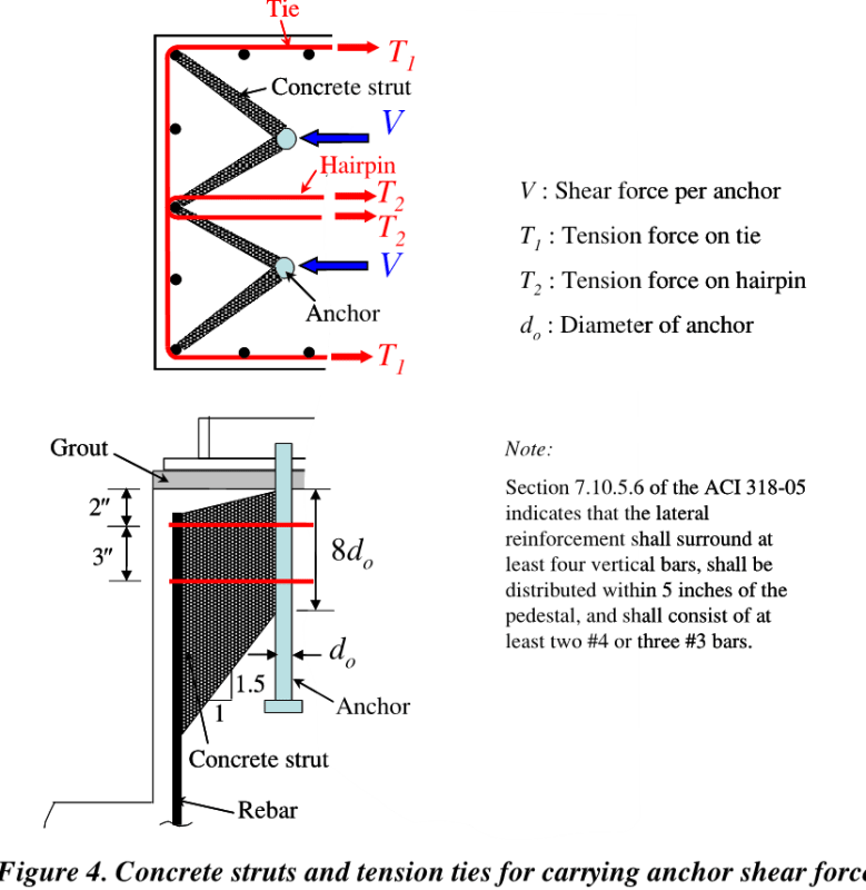
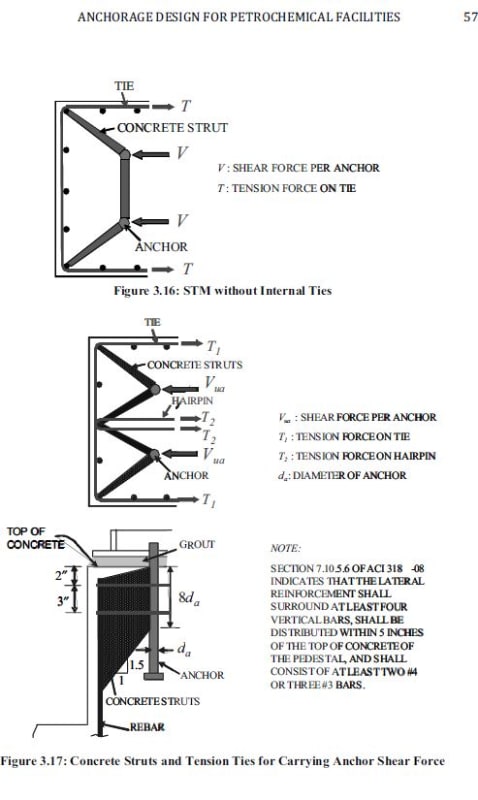
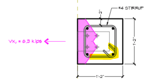
3. For tie reinforcement, and with reference to Figure 3.18, the following assumptions are suggested:

a. Only the uppermost two layers of ties (assume two #4 ties within 5 in. (127 mm) of the top of the pedestal as required by ACI 318 Section 7.10.5.6) are effective.

b. Tie reinforcement should consist of ties with seismic hooks. If internal ties are required, hairpins could be used. As an alternative, diamond-shaped ties can also be used.

c. The location of hooks and the direction of hairpins should be alternated as shown.

d. If the available development length of hairpin, ldha, is shorter than the required straight development length for a fully developed hairpin, ldh, the maximum yield strength that can be developed in a hairpin is: Fy x ldha/ldh

where Fy is the yield strength of the hairpin. If ldha is shorter than 12 in.(304.8 mm), (that is, the minimum development length based on ACI 318 Section 12.2.1), then a hairpin should not be used.

e. Away from the hook, the tie is assumed to be fully developed. For example, under the shear force Vua, the tie on layer A can develop Fy at nodes 1 and 6

f. At the node where the hook is located, the tie cannot develop Fy. For example, under the shear force Vua, while the tie on layer A can develop Fy[/sub at node 6, the tie on layer B cannot, because the hook of the tie on layer B is located at node 6. In order to calculate the contribution of the tie on layer B to the tension tie at node 6, and with reference to Figure 3.19, the stiffness of a hooked bar bearing on concrete (Case 1 - smooth rebar with 180° hook bearing in concrete [Fabbrocino et al., 2005]) is compared to the stiffness of a hooked bar bearing on rebar (Case 2 - the conventional single-leg stirrup with reinforcing bars inside the bends [Leonhardt and Walther, 1965 as cited in Ghali and Youakim, 2005]).

Even though the capacity of Case 2 may be higher than that of Case 1 because of bearing on rebar of a larger size than the stirrup, contact may not always be present because of common imprecise workmanship. When the contact is not present, Case 2 is assumed to behave as Case 1. Leonhardt and Walther (1965) found that in order to develop fy on the bends of 90°, 135°, and 180° hooks when engaging bars located inside the bends (Case 2), there was a slip of about 0.2 mm (0.0079 in.). Based on the test results of Fabbrocino et al. (2005), the stress that was developed at the hook of the smooth rebar with a 180° hook bearing in concrete when it slipped 0.2 mm was about 20 ksi (138 MPa). Therefore, it is assumed that the tie can only develop 20 ksi (138 MPa) at the node where the hook is located.
 
Bones206 said:
The J-bolt is the highlighted part, with embedment depth starting at the breakout plane. I'm not saying that this approach is the only correct way to look at it, just that it's a conservative approach.

Thanks for the clarification. I thought that you were doing the J-bolt thing on the other side of the crack. I agree that's a conservative approach where you're using it. I'll check out the Petrochemical stuff. That's clearly advanced the Widianto method some from when I last looked at it.
 
Thank you very much gusmurr.

Gotta love academics always botching the fundamental detailing.


C01_aah37o.jpg
 
Status
Not open for further replies.

Part and Inventory Search

Sponsor