Continue to Site

Eng-Tips is the largest engineering community on the Internet

Intelligent Work Forums for Engineering Professionals

  • Congratulations cowski on being selected by the Eng-Tips community for having the most helpful posts in the forums last week. Way to Go!

Anchor Reinforcement Detail for Circular Pier Foundation Anchorage 1

Status
Not open for further replies.

LockeBT

Structural
May 9, 2021
55
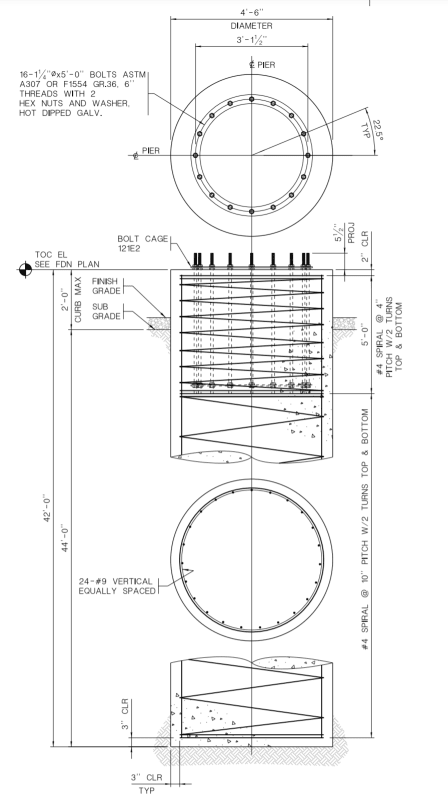
I am having trouble with concrete breakout (yayy thanks alot overstrength factor) on a pier foundation with circular anchor bolts pattern. Planning to utilize anchor reinforcements per Sect. 17.4.2.9 of ACI 318-14 to preclude breakout. However I am not quite sure how to detail it especially when my anchors will be a giant bolt-cage.

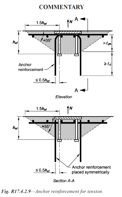
Also, fig. R17.4.2.9 suggests the use of surface reinforcement (shown below), is there a way of detailing to by pass this?
Anchor_Reinf_k6oqe5.png
 
Replies continue below

Recommended for you

I looked to 17.4.2.9 and R17.4.2.9 ... and the following is copy paste for the reinf.

.... The anchor reinforcement should consist of stirrups, ties, or hairpins placed as close as practicable
to the anchor...


If you need anchor reinf. for tension, you need to provide reinf.( hair pin etc) similar to the shown fig. R17.4.2.9 . The surface mesh reinf. could be effective for shear . Refer to fig. R17.5.2.9b—Edge reinforcement and anchor reinforcement for shear.

The foloowing excerpt from PIP STE05121

anchor_pull_ot_rebar_fxyxbc.jpg


If you post more details , you may get better responds..
 
Thank you for your response.

Here is my current detail without tension anchor reinforcement. The circular bolt pattern might prove it challenging to provide hairpins each bolt.

I was learning towards the justification that since my longitudinal reinforcements are within 0.5hef of the anchors, they can be considered to effectively serve as anchor reinforcement in tension?
Detail_epbpyw.png
 

In this case yes ...but you can not consider all of the longitudinal reinforcements to serve as anchor reinforcement in tension if moment governs ..

For instance,if Moment (Mu) = 700 kip-feet T ≅ 700/(0.8*4.5) = 195 kips. This tension force will be resisted effectively by 5 anchor bolts .

So, around eight of # 9 rebar out of 24 longitudinal reinforcements WILL resist this tension load.

Approx.Steel capacity = φNn =0.75*8*36= 218 kips so O.K.

If you provide base plate details, concrete class, Moment (Mu) ,Shear (Vu) ,Tension (Nu) you may get more refined calculation..
 
It is note common to use upper mesh at the end of pile. In my judgment, if the length of anchor bolt is enough, base on the failure mode shown in the following image, there is no necessary to use upper mesh. Moreover, if it is necessary, the standard hooks with straight extensions at the end of longitudinal reinforcements can act as upper mesh. You can use HILTI software to check in detail.
Untitled_pzwo2g.jpg
 
AE Seif, thanks for the suggestion. Perhaps if spacing permits I might add a 90 hooks for (some of) my longitudinal bars. Albeit it might be too congested at the top of the pier and those hooks will interfere with my bolts. Construction will hate me. But they already haha.

HTURKAK, Appreciate the offer. I have already ran the calculations you have done in the comment. I was able to find the compression blocks and tension zone based on the moment+axial loading.

This stems an unrelated non-anchorage question, for square or rectangular members, developing the M-P interaction diagram is simpler due to their shapes. For circular sections, the compression zone area isn't simply 0.85ab, it's 0.85 x an area of a semi-circle with more complicated equation. To put it in a spreadsheet it was a nightmare for me since that area is changing depending on the point on the interaction graph. Any suggestion to make this an easier calc? Some textbooks suggest that I treat the circular column or pier as a square column with 0.8xdiameter as each side. I don't typically agree with this approach.
 
In this scenario, if the #9 are developed both above and below the potential breakout failure plane, why would you need additional anchor reinforcement?

 
LockeBt:
you can grab my spreadsheet from here for P-M curve with circular sections, allows the Whitney Block or PCA's parabolic stress block.
Link

User IDS also has their spreadsheet which is faster than mine and covers various units and national codes:
Elastic Analysis:Link
Ultimate Analysis:Link


My Personal Open Source Structural Applications:

Open Source Structural GitHub Group:
 
@ azcats, a few comments down, my initial justification was that the #9 longitudinals would act as anchor reinforcement in tension. I just wasn't too confident with that judgment. However I think I'm more confident about it now.
 
Status
Not open for further replies.

Part and Inventory Search

Sponsor