Continue to Site

Eng-Tips is the largest engineering community on the Internet

Intelligent Work Forums for Engineering Professionals

  • Congratulations waross on being selected by the Eng-Tips community for having the most helpful posts in the forums last week. Way to Go!

Anchorage of threaded rod in concrete 2

Status
Not open for further replies.

bugbus

Structural
Aug 14, 2018
515
What is normally the minimum requirement for anchoring a threaded rod into a concrete footing? (Assuming that there is enough reinforcement and sufficient edge distance to avoid a cone type failure or some other failure of the concrete.)

Our standard practice would normally be a plate, e.g. 50x50x6 or 75x75x8 or similar dimensions depending on the rod size, with a nut above and below the plate.

I have been reviewing some drawings by another consultant and they have specified a nut with a standard washer only. It seems that this would potentially crush the concrete above the washer.

I have also seen previously a single nut being used, which has a similar concern but even worse.

Any ideas?
 
Replies continue below

Recommended for you

I don't believe local crushing of confined concrete would generally be considered for the case of an anchor bolt. The size of the washer/nut/plate/head only is considered in regard to how it affects the perimeter of of the failure cone.

Rod Smith, P.E., The artist formerly known as HotRod10
 
What sort of load are you looking at? and what size bolt/nut? I normally don't use a washer or a plate washer.

Rather than think climate change and the corona virus as science, think of it as the wrath of God. Feel any better?

-Dik
 
Thanks for the replies so far

These are M20 and M24 Grade 8.8 rods with design loads of about 120 kN and 160 kN respectively.

From my quick calculations, based on the standard washer size, the stress on the concrete would be in the order of 100-120 MPa. The specified concrete strength is 32 MPa.

Even allowing for confinement (our standard allows a design bearing stress of up to 1.08fc), I would have thought that this would require a 60x60 and 70x70 plate respectively.

 
I think testing has shown that a headed stud will suffice for most anchorages.

It makes sense, in that plate needs to flex to see the full load, but the force is attracted to the much more stiff area in direct compression right above the head or not on the stud before the plate can flex.
 
Another thought I have had is that the end of the rod would not see the full load, because a lot of the load is transferred via bond similar to conventional reinforcement. Although how much exactly would be hard to quantify. Potentially could treat the rod as though it were a plain (undeformed) reinforcement bar and reduce the end anchorage force accordingly.
 
AISC's Design Guide 1 (Base Plate and Anchor Rod Design) recommends just using a heavy hex nut or a head on the rod since this usually provides enough pullout strength so that the steel fails in tension before pullout occurs, unless you are using high strength anchors in low strength concrete.

The ACI formula for the pullout strength of a headed stud or headed bolt, which is just a check of local crushing at the anchor head, uses 8*Bearing Area*f'c, so you get a lot more capacity than a normal concrete bearing check. You need to check both failure modes, though, to see if a washer will help you at all.

Structural Engineering Software: Structural Engineering Videos:
 
Thanks again everyone

That 8*f'c limit seems to be the key here and would solve this issue for me.

At first I was not aware of any equivalent bearing stress limit in the Australian codes, but after checking again, there is a limit in AS 5216 of 7.5*f'c (or 10.5*f'c for uncracked concrete), although this is for an anchor channel with several consecutive anchors. There is no mention of the same bearing stress limit for a single anchorage. However it would make sense that this should be the same.

That limit of 1.08*f'c (i.e. phi*1.8*f'c where phi = 0.6) that I mentioned previously is for a concentrated load on the external face of a concrete element, which I agree is a different situation.
 
You also have to be cautious if using plate washers that you don't introduce a plane of weakness caused by the plate washers.

Rather than think climate change and the corona virus as science, think of it as the wrath of God. Feel any better?

-Dik
 
Yeah I never liked the wide plate washer detail either…


Is anyone aware of any cases where bolt head (or single nut) does actually govern?
 
Determining if the steel strength or pullout strength controls depends on the anchor diameter and the material properties of the anchor and the concrete, but I can give you a few data points.

For a 1-1/2" diameter, F1554 Grade 36 anchor (Fu = 58 ksi), steel strength and pullout strength will be approximately equal for a f'c value of 3.5 ksi.​

For a 1-1/2" diameter, F1554 Grade 55 anchor (Fu = 75 ksi), steel strength and pullout strength will be approximately equal for a f'c value of 4.5 ksi.​

For a 1-1/2" diameter, F1554 Grade 105 anchor (Fu = 125 ksi), steel strength and pullout strength will be approximately equal for a f'c value of 7.5 ksi.​

Using a higher strength concrete means the steel will fail before pullout occurs. Also, AISC's Design Guide 1 warns that using unnecessarily large washers can reduce the concrete resistance to pull out, as others have mentioned. They can also interfere with reinforcing and make it harder to consolidate the concrete.

Structural Engineering Software: Structural Engineering Videos:
 
Thanks for the added info... almost always use Grade 55 S1. I like anchor rods to be weldable and Gr 55 and 36 are nearly the same cost.

Rather than think climate change and the corona virus as science, think of it as the wrath of God. Feel any better?

-Dik
 
ProgrammingPE said:
Also, AISC's Design Guide 1 warns that using unnecessarily large washers can reduce the concrete resistance to pull out, as others have mentioned. They can also interfere with reinforcing and make it harder to consolidate the concrete.

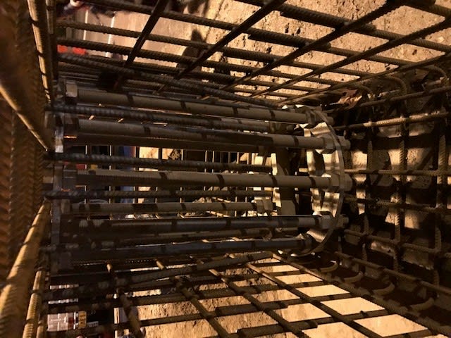
I wonder how everyone feels about steel plates/strips/rings being cast into a footing as a template for the anchor bolts then? This is a pretty common detail from what I've seen.

An example I worked on recently is in the photo below. These were M42 bolts supporting a large sign gantry. There are two of those ring templates, at the top and bottom of that pile cap rebar cage, 75 mm wide plate, 20 mm thick.

9_atgzjn.jpg
 
I don't think that's pulling out any time soon.

Not much lap on the side bars though...
 
Tomfh said:
Not much lap on the side bars though...

I knew someone would have pointed that out (and happy that everyone is switched on) - Those were welded by preference of the cage fabricator
 
but, a definite line of weakness... have to treble the stirrups in that region.

Rather than think climate change and the corona virus as science, think of it as the wrath of God. Feel any better?

-Dik
 
The ring plates, as a percentage of the typicall concrete section it's embedded in, is not that much. They're also embedded several feet into the concrete, and loaded primarily in bending, so one side is in compression, when the other is in tension. Anyway, We've got hundreds around my state and thousands around other states, embedded in 4' diameter drilled shafts (7.5' to 'lap' with the reinforcing steel), supporting 120' light towers, some for more than 30 years in the Wyoming wind. We haven't had a structural failure of one yet, and to my knowledge, neither has anyone else. The base plate to pole welds are where we have problems.

Rod Smith, P.E., The artist formerly known as HotRod10
 
They take up a fair part of the area and will be resisted by the stirrups or any overlap by the pile reinforcing (assuming one is in the vicinity). They are also 'ultra hard' compared to the concrete and would generate high tensile stresses at the corner where they meet the concrete.

When I worked at DB about 55 years back, Manitoba Hydro had anchorages for high loads. I was surprised that they were like spirals for screw piles. The shift engineer explained that this was chosen because the spiral did not produce a line of weakness.

Rather than think climate change and the corona virus as science, think of it as the wrath of God. Feel any better?

-Dik
 
I'm not sure why the 'line of weakness' is necessarily detrimental.

As long as you have enough reinforcement crossing the potential failure plane, to satisfy strength and control cracking, what's the issue?
 
Status
Not open for further replies.

Part and Inventory Search

Sponsor