Continue to Site

Eng-Tips is the largest engineering community on the Internet

Intelligent Work Forums for Engineering Professionals

  • Congratulations KootK on being selected by the Eng-Tips community for having the most helpful posts in the forums last week. Way to Go!

Angular displacement backlash

Status
Not open for further replies.

DiamondDave

Mechanical
Jan 27, 2009
51
Hello guys, ive been trying to work something out that is likely contributing to crane skew.


So a loose keyway was found on the drive shaft which has resulted in elongstion on the coupling and shaft keyways thus crating backlash. Id say approximately 12mm of play exists here now.

Both crane drice wheels are driven by a common shaft so this play results in one side driving befoee the other.


I would like to try and work out how much further one side drives before the other side catches up.


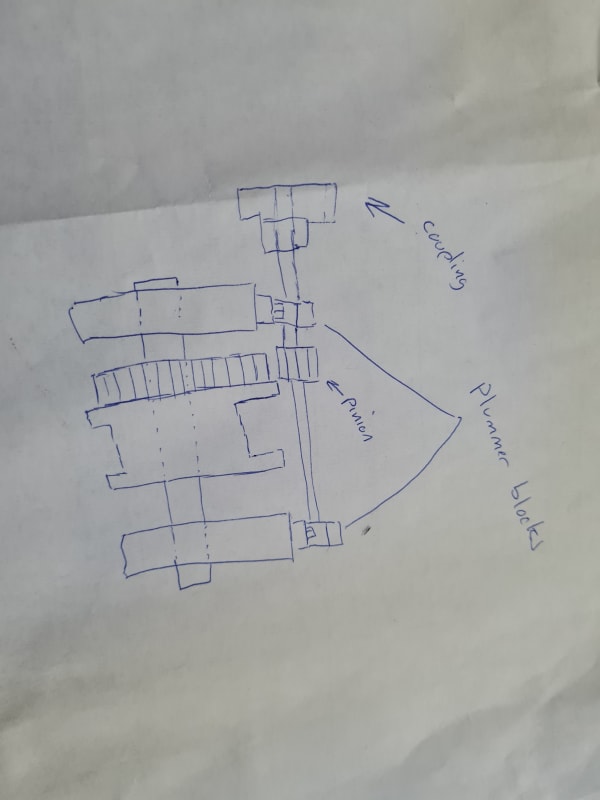
The drive shafts contains a pinion at each end which connects to a large gear ring attached to the drive wheels.

Ive attempted to work it our bur I feel that the displacement I get is far too large but then again could be entirely possible.
 
Replies continue below

Recommended for you

Hi Diamond Dave

A sketch would help however I assume this 12mm play is a radial gap, so if say the mid radius of this gap is 25mm You can estimate the angular displacement thus

12mm = r* theta Theta in radians

12/25 = theta = 0.48 which = 27.48 degrees

So the coupling would have to rotate 27.48 degrees before picking up any drive.

“Do not worry about your problems with mathematics, I assure you mine are far greater.” Albert Einstein
 
Hi Desert fox, thanks for the reply.

Ive left my sums in work but that does sound close to what I got. The shaft/couples with the play then have to turn this distance before picking up drive as you say. Can you tell me how to work out how much further the side without backlash will drive? The drive shaft is on a pinion which drives a gear ring attached to the wheel. The diamter of the wheel is approximately 24 9/16 inches.

 
Hi Diamond Dave

If I understand correctly and on the side with no backlash and assuming they move together then the no backlash side would drive the same angular distance again assuming both wheels are the same diameter. Now one thing that's not been mentioned is wind up of the shaft, what I mean is one side is driving and is therefore taking all the driving load until the back lash is zero. If you can provide some sketches and sizes of shaft etc we might be able to help further.

“Do not worry about your problems with mathematics, I assure you mine are far greater.” Albert Einstein
 
Hi that sounds spot on what you are saying.

The side with the backlash isnt being driven whilst the other side is. Which is causing the crane to skew in my opinion.


Im just trying to work out the exact figure of skew as a mental exercise and also to use it to prove how bad it is.

Ill try get a drawing for you tomorrow.
Cheers
 
Hi Diamond Dave

I have seen stuff like this before, I recall a mechanism which had angular wind up in the shaft due to an offset spring load, I cured it by making the diameter of the shaft 1/8" larger.
Yes the crane needs to be sorted before some failure occurs.

“Do not worry about your problems with mathematics, I assure you mine are far greater.” Albert Einstein
 
I dont have sizes to hand but previously id discovered a crane skewing and found the wrong size of bolts were put into the couplings, metric was used.instead of imperial and the holes were elongated and caused backlash.

I checked for that in this crane and it was fine but another shift found the elongated keyway where the coupling joins the shaft and removed it to the shop where I was tasked to strip it down its apparent to me its been worked on before as the key didn ot look like key steel, it looked more like an ordinary bit of plate ir bar so I dont know how good a fit it was. I also noted that bolts on the plummer block end cover plates were replaced with metric ones. The bolts on the top cover were also stretched.

My opinion is the pinion drove over the rim of the wheel and caused damage to the plummber block bolts and possibly the coupling closest to it, its been repaired but the root cause not fixed.
 
Hi Dave

Not fully understanding how a pinion drove over the rim of the wheel etc, perhaps you can explain it to me better with some photos of the failure?
If metric bolts were used in place of imperial bolts then IO can imagine that might cause a problem especially if the bolts were incorrectly tightened and or a different bolt grade.

“Do not worry about your problems with mathematics, I assure you mine are far greater.” Albert Einstein
 
I hope this helps.

So the coupling had elongated key ways on the shaft and coupling. The key in that looked like it was just a bit of ordinary steel bar.

The bolts on the top covers of the plummer blocks were stretched in the section that was not mating with the female threads of the bottom cover right where the two halfs separate.

These are old style blocks so they have metal end covers rather than rubber seals. These were where metric bolts were used instead of imperial. Its not load bearing but was certainly loose and I suspect have been knocked out previously by the pinion mounting the rim/flange of the crane wheel due to excessice float.

I believe the root cause of the damage was not resolved and the bolts wete simply replaced with the wrong kind and the top cover tightened down again.

Im just wondering if the excessive play ij the key way contributed to the excess wear of the wheel flanges/rims to allow the pinion to mount the flange and pop the top covers or its a separate issue.

The pinion is also worn away on the side that would be closest to the rim which again suggests to me it has been rubbing!.


20211213_090854_l4ghcx.jpg
 
Hi Dave

I agree with you or at least it sounds very plausible, if the bolts weren't tightened down correctly and because there might have been a bigger clearance between the Plummer block bolt hole and the metric bolt, then its likely the plummer blocks moved. Once the blocks move its possible then, that excess pressure was placed on the coupling key/keyway and hence the distortion you now see. Its also very likely that the pinion did foul the crane wheel, however if we had some photos and or some dimensions along with material grades etc we could possibly tie it down further.

“Do not worry about your problems with mathematics, I assure you mine are far greater.” Albert Einstein
 
The holding down bolts for the block top covers were imperial although they were actually set screws not bolts so I am wondering if that would have allowed some play.

Metric bolts were fitted on metal covers which the shaft runs through and attach to either side of the plummer blocks.

No idea of material specs im afraid but I could try and get some pictures at some point.

The pinion side which would be closest to the wheel flange actually has the teeth worn down about half an in into the pinion and about 3/4 of the depth of the teeth.
 
Hi Diamond Dave

Some pictures would help and the size of metric bolts or set screws used and what the imperial size was, also very important the material grade for both metric and imperial bolts (metric bolts have grade number stamped on the hex head)and tightening torque because what I am thinking here is that metric and the imperial bolts should be tightened to different torques but we need to know what the maintenance book states about the torque.

“Do not worry about your problems with mathematics, I assure you mine are far greater.” Albert Einstein
 
Be lucky to find a book for this crane....

The metric bolts were m6 the imperial ones were 1/4 whitworth. So to be honest the m6s shouldn't even have fitted.

The top cover bolts were 5/8 whitworth and these had some stretching just before they mated with the bottom cover threads.

In this scenario im not sure the part with mixed bolts would have caused such failures. The plates were loose but they arent load bearing.
 
Status
Not open for further replies.

Part and Inventory Search

Sponsor