Eng-Tips is the largest engineering community on the Internet

Intelligent Work Forums for Engineering Professionals

  • Congratulations waross on being selected by the Eng-Tips community for having the most helpful posts in the forums last week. Way to Go!

Another interesting bridge 1

Status
Not open for further replies.

spsalso

Electrical
Jun 27, 2021
942
US
We've talked about the railroad bridge over Highway 101 at Ventura CA, and the addition of unnecessary steelwork thereon.

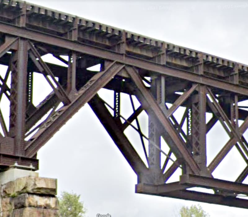
Here's another one, but I doubt there's anything unnecessary. In fact, it visually feels like something is missing.

The bridge is at Cuttingsville, Vermont.

Here's an exceptionally artsy picture:


Of interest to me is that the outer two spans are cantilevered off of the center span. I believe that is highly unusual, perhaps unique.

Here's another shot:


I'm interested in opinions of why this unusual design was chosen. If it was a good idea, why is it so unusual. If it was a bad idea, why? Note that the bridge has been around for awhile (as opposed to, say, a certain bridge in Genoa), so it probably actually does work.


What say you?


spsalso
 
Replies continue below

Recommended for you

Do you know the age of it? I think that style was common 50 or 75 years back... even at the time of rivetted structures.

Rather than think climate change and the corona virus as science, think of it as the wrath of God. Do you feel any better?

-Dik
 
Cantilever and drop in framing is common in roof structures. Maybe not so much in rail bridges, but there is nothing unique about it.
 
I would put the bridge circa 1900 because of the stone piers. I agree with hokie66 that it's a little odd to have a drop in span on a rail bridge. Perhaps they were looking to minimize the pier widths or may have been easier to construct because of the terrain.
 
If anyone can come up with another railroad bridge, or even another bridge, that is designed in a similar manner, I would appreciate it.

The bridge has been in use for over 100 years. The lead locomotive in the first shot weighs 390,000 pounds. This bridge WORKS!

One thing of note is that the center span MUST be in place before the outer two spans are installed. This means that you can't build towards the center, from the ends. You can't hoist up the center span with cranes rigged on the outer ones.

One could wonder at the assembly process for this bridge, and whether that tended to limit enthusiasm for trying it again, elsewhere.


spsalso
 
Of interest to me is that the outer two spans are cantilevered off of the center span. I believe that is highly unusual, perhaps unique.

Somewhat unusual for a truss, but steel girder bridges with pin and hanger joints, which do basically the same thing, were a somewhat common design decades ago, and many are still in service today.

Rod Smith, P.E., The artist formerly known as HotRod10
 
The bottom horizontals that are missing on this bridge are basically the same ones as the faux members on the Ventura 101 Bridge. If present, they would need to be allowed to slip, to avoid introducing tension into joint at the top. So, adding them would serve no structural purpose. Unlike CalTrans, the railroads typically don't add things for aesthetics.

Rod Smith, P.E., The artist formerly known as HotRod10
 
Yes, but pin and hanger joints are no longer used because of corrosion issues and because they are fracture critical. There was at least one major failure.

The Vermont bridge does not appear to have that type connection.
 
Yes, but pin and hanger joints are no longer used because of corrosion issues and because they are fracture critical.

Correct. They have to be monitored carefully.

The Vermont bridge does not appear to have that type connection.

I just mentioned the pin and hanger as another type where the main span has a cantilever with a hinge joint and a simply supported end span.


Rod Smith, P.E., The artist formerly known as HotRod10
 
The primary advantage of the configuration of these truss spans is that all the members carrying significant compression are at the top, where they can more conveniently be braced against buckling.

Rod Smith, P.E., The artist formerly known as HotRod10
 
BridgeSmith said:
The primary advantage of the configuration of these truss spans is that all the members carrying significant compression are at the top, where they can more conveniently be braced against buckling.

All? Those four diagonal members on the outer end of the center span are certainly in compression. And not at the top.

And I don't see that this design is any improvement on the more typical deck truss design as far as being braced against buckling. Nor why being at the top is much more convenient.


spsalso
 
Also of some interest, though not on the large visual scale of the overall bridge:

Cuttsville_Bridge-1_pb8gsf.jpg


Note that the cantilever joint is distinctly not pin-connected. Seems kind of strange, considering there is no other member that could halt rotation about that joint. Of course, if the tops of the bridge supports NEVER change comparative height, it shouldn't matter.


spsalso
 
All? Those four diagonal members on the outer end of the center span are certainly in compression. And not at the top.

My apologies. I meant to say all the horizontal members carrying significant compression are on the top.

Note that the cantilever joint is distinctly not pin-connected.

It's effectively a pinned connection, in that it won't carry significant moment (relative to the remainder of the truss).


Rod Smith, P.E., The artist formerly known as HotRod10
 
Yes, I would certainly call that a pin, even though the top chord appears to be continuous. I wonder how that bridge was erected.
 
Hmmm. So we have here a pin-less pin joint. I would think, then, that there could be pinless pin and hanger joints, too.

However. As funny (to me) as the joint is, it has proven itself through 125 years. Something that certain other bridges have failed to do.


spsalso
 
To some degree, creating these pin joints (whether physical pins or simply areas of limited rotational stiffness) could have been used to simplify the analysis with minimal impact on design economy, given the methods of the time. Even if it wasn't used (as often was the case) to simplify erection in areas with limited access.

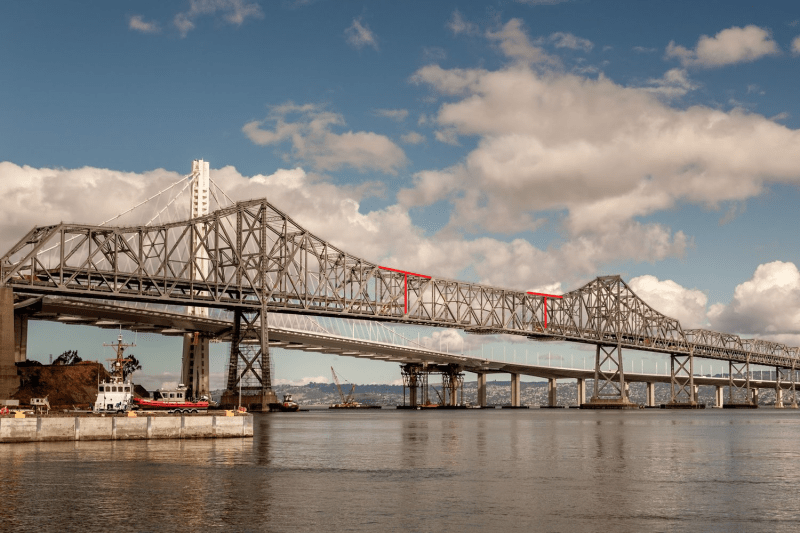
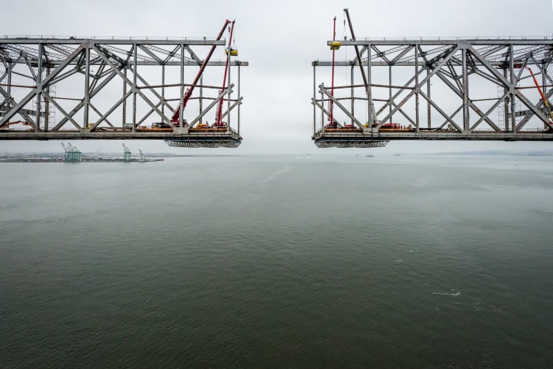
Yes, many cantilever structures with drop-in spans were constructed with faux-chords (and slotted connections) at the hangers. Or in some cases, a temporary chord was installed with a jacking mechanism to allow cantilever construction methods before the deck was placed, then later released to create the suspended span condition for full service loading. The SFOBB eastern span (and possibly Tappan Zee, Goethals and Carquinez bridges?) were examples of this method. I was privileged to be part of the dismantling of several of those bridges.

----
just call me Lo.
 
"faux-chords"? "temporary chord"?

Where is this coming from? I see nothing here that is faux or temporary.

I suggest that every piece of the bridge you are looking at has been in place for over a century. Not faux. Not temporary.


spsalso
 
No, on this bridge, they have not put in faux chords (and I don't see any detailing indicative of temporary chords used during erection).

You postulated that this is a very unique structural system. It in fact is not -- just that often, other bridges using this system are camouflaged -- at times, to prevent that feeling of having "something missing" for members of the general public.

SFOBB_iyuanx.png


In this picture, the noted top chords are not performing any real structural function in the bridge during its service life -- "only" there to reassure the public. In your bridge, they were omitted. In this case, both during original construction and demolition, the "faux" chords were temporarily connected to allow us to do this:

bay_bridge_demo_burbank-dsc_3794_36710426_ver1.0_ot3r2w.jpg


----
just call me Lo.
 
So you're saying the example bridge is a cantilever bridge, and thus common?


spsalso

 
Status
Not open for further replies.

Part and Inventory Search

Sponsor

Back
Top