Eng-Tips is the largest engineering community on the Internet

Intelligent Work Forums for Engineering Professionals

Another Question about water tank design.

Status
Not open for further replies.

sdz

Structural
Dec 19, 2001
555
0
16
AU
I’d like some advice for a design I’m working on for a water tank. I have reached a conclusion of my own but I’d like to hear some more opinions.

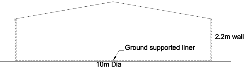
This is a typical bolted tank with a membrane liner. There are corrugated steel walls and roof and no base. The liner sits directly on the ground within the walls and runs up the inside of the wal and is screwed to the top ring beam. Nominal dimensions are 10m dia and 2.2m wall height.
Tank_section_sketch_qesuqs.png


Now when calculating uplift
(a) Can I assume there is some minimum level of water in the tank?
(b) How do I calculate the contribution this makes to overturning resistance?
 
Replies continue below

Recommended for you

How is this another question, it is the same question you posted the other day.
a) Are there any foolproof controls on the minimum liquid level?
b) You would have to consider the strength of the membrane. However, if the answer to a) is none, then it doesn't really matter, you would be limited to the weight of the shell and roof (which for a corrugated tank is not much). Perhaps there is a minimum draw-off height for the outlet nozzle?

These tanks can be purchased as standard products, likely more economical than redesigning. Typically they would not be held down so I would assume have to rely on the strength of the membrane with a minimum liquid level. The membrane is quite strong but flexible, so I believe it is a more empirical/historical verification of the uplift capacity of the membrane with a minimum liquid level the vendors must use. When these designs have been independently verified in the past, I know the same conclusion regarding requirement for hold down bolts was determined.

My guess is a low recurrence interval is also used on these designs. Where is yours located and what wind loading parameters are you using?

Check out the aquamate website, they have some drawings of the pad preparation, sitting on dirt no hold down for standard designs.
 

Dear sdz (Structural), It is not reasonable to assume that there will be some minimum level of water in the tank ..The proposed minimum amount could evaporate ..Moreover, the membrane will not resist to OT of the tank . When uplift starts due to OT, the membrane will be dished and the minimum amount of water flow to the opposite side.

My suggestion will be , check the OT and sliding of the tank assuming only the shell and roof wt will resist.O.K., I will understand the use of reduced FS ( e.g. 1.2 ) but less than one should not be acceptable. If you can not obtain a reduced FS, propose the use of anchors and RC ring foundation (say 1 ft H, 3 ft W and interior compacted sand+ gravel ) ..

If I were in your position, and a if a minimum FS is not justified, I would suggest the proposed solution and if the client declines, the only option for me would be to pack up and leave and suggest to the client that it would be better to hire somebody else ..

 
sdz,

All said and done, a tank that size I'd expect anchoring. I also agree with BJI, why re-invent the wheel?

But if you want to continue down this path, I'd recommend not considering any water present for wind when assessing overturning or sliding of your tank.

Follow AS/NZS 1170.2 for appropriate drag on tanks/bins/silos and don't forget roof uplift, including local pressure factors.

Follow AS/NZS 1170.0 guidance on stability combinations and treat all dead loads tending to stabilise the system with a 0.90 reduction factor.

AS 1418 crane code has some helpful advice regarding stability, may be worth looking into that also. Basically factor down stabilising components and factor up de-stabilising components and aim for a margin of stability above 1.
 
Thanks for the advice.

I have decided to follow API 650 and allow the tank half full at the time of the ultimate wind (ARI=500 years). Most of this will be taken on the ground and won't resist uplift and overturning. Considering slip between the liner and the wall only a small amount of resistance can be mobilised. I've taken this as a maximum on the windward face reducing to zero on the centreline, i.e. as a crescent load on the windward half. I've also used a smaller load factor for this, an extra factor of 0.8 on top of the 0.9 used for dead load, 0.9x0.8=0.72.


Status
Not open for further replies.
Back
Top