Continue to Site

Eng-Tips is the largest engineering community on the Internet

Intelligent Work Forums for Engineering Professionals

  • Congratulations GregLocock on being selected by the Eng-Tips community for having the most helpful posts in the forums last week. Way to Go!

ANSYS friction heating problem

Status
Not open for further replies.

Skeltor

Mechanical
Jun 2, 2017
4
Hi everyone,

I am now working on a project during my internship. I have to modelise a worm gear in ANSYS to determine the heat and temperature produce by the friction of worm gear.
I know how to use ANSYS for Modal and Structural modules but never use the other.
I have done many research on internet and can't find something which suit to me.

This video help me but I can't achieved a model without errors, it doesn't work at all : (I tried with the APDL command to add temp value to my elements)


Have you got any idea (or a tutorial would be perfect) which can help me to modelise this worm gear and have good results?

Thank you !
 
Replies continue below

Recommended for you

Hi everyone,

I precise my problem a bit more :

I have to simulate a wrom gear with a drive worm on ANSYS. For that I use Transcient Structural analysis but I can't succeed to simulate the motion.

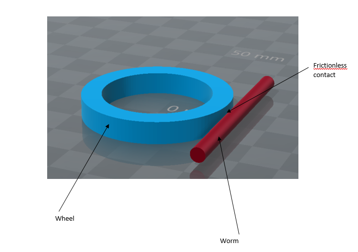
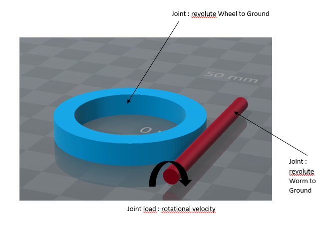
I have tried to use the joint by apply a worm to ground revolute and a wheel to ground revolute. After that i put a joint load to impose my rotational velocity but it doesn't work at all. I use frictionless contact for the moment.

it is the first time that i use joint, i succeed on a simple rotation around a shaft but don't find the solution for my study case.

Can you help me please to set the correct model on workbench? Don't hesitate to ask me more details

Thank you and sorry for my bad english,
 
Maybe you could post some pictures of your model (contacts, boundary conditions, loads) and results (or error messages).
 
It is difficult for me because the company where I am is very strict about the information which go out of the company. I don't have internet connection on the computer I use I only have access to the company network to work.
I have to use my own computer without ANSYS or CAO files to post on this forum.

I will try to take some screenshots
 
I can't send you pictures, I have done a schematics of principle to show you my boundaries :
qqdfgq_rkr1aw.png
wsdfh_z9giel.png


Error message : The solver engine was unable to converge on a solution for the nonlinear problem. Please see the troubleshooting section of the help system for more information.
Warning : The unconverged solution (identified as substep 999999) is output for analysis debug purpose. Results at this time should not be used for any other purpose.


Thank you,
 
Status
Not open for further replies.

Part and Inventory Search

Sponsor