Eng-Tips is the largest engineering community on the Internet

Intelligent Work Forums for Engineering Professionals

Any room for improvement on this drawing?

Status
Not open for further replies.

rollingcloud

Aerospace
Aug 9, 2022
167
0
0
US
GD_T_Case_6_j0u2co.png


The function of the rod is to provide a platform (datum C) for a spring and a sealing surface (datum B), when pressure is too high, the rod moves to the right.
My main concern is the feasibility of the total runout over short distance. (Datum D is not critical, guided by a bushing to prevent too much misalignment.)
 
Replies continue below

Recommended for you

Datum feature C definition with A-D primary and B (the cone) secondary does not look kosher.
Use customeized DRF (x, y, z, u, v w, ) if you really want to use B as secondary.
 
Greenimi,
Thanks for the comment! Would it be better to set the conical surface as tertiary datum and set the spring platform as the secondary datum? I am not familiar with customized DRF.
 
If you don't want to use customized DRF (or you don't know to use it per 2009)--yes, I know I assumed Y14.5-2009 standard is used, then use A-D primary as you already have, C secondary (and remove B secondary for the cone's
vertical flat surface/ face definition) and use profile for the cone to A-D primary and C secondary.
Then if you name the cone datum feature B or not that's another issue. You can, but I don't see the point, at least not at this time.
Maybe if you use the cone (B) to define other features ....which are not currently part of this discussion.
 
The perpendicularity for C is fully constrained by [A-D] The reference to adds no constraint.

Total runout is fine over a short surface. The angle should be basic for total runout to cut back the difficulty of fitting a solution to the data provided.
 
Thanks Greenimi & Dave,
(I just read a little bit about customized DRF, it looks like its about removing excessive freedom constraints from a particular datum.)
I made the corrections:
GD_T-spring_rod_zlptow.png

If the conical surface is not part of the DRF, the part is only constrained by datum A and B, that means the part can still move to the left during inspection/machining, right? or I am really confused.
 
rollingcloud said:
part is only constrained by datum A and B, that means the part can still move to the left during inspection/machining, right?
First off, the datum features in the drawing apply at inspection but may or may not apply at machining. Machining datums may differ from the drawing datums. The requirements apply to the finished part during the acceptance evaluation.
To see if and when the part can "move to the left" consider how it is held for inspection for each requirement; in your last image the runout and perpendicularity tolerances only reference datum A (axis) so at inspection of those requirements the part can move in the degrees of freedom not taken away - which is the axial translation (left and right) and rotation about the datum axis. The parallelism tolerance references datum B (shoulder face), so when the part is inspected for that it contacts the fixture at that face and is oriented according to it. Technically it can't move right and left, however this is an orientation control, therefore the tolerance zone can float right and left, and that translation is not considered as a constrained degree of freedom (only two rotations are constrained).
The datum feature selection and their order in the feature control frame should mimic the assembly application.

The total runout on the cone with the basic angle with reference to datum axis A is essentially identical to a profile of a surface tolerance with same datum reference. The resulting tolerance zones are the same, and I think profile would be more straightforward in this case (only because it's a cone and not a cylinder).
 
rollingcloud,

Dynamic profile would be equivalent since the controlling diameter is not basic. One could replace the perpendicularity tolerance with profile, but that is not necessary.

What B might have noted is that even in 2018 the standard does not specify a tolerance zone for total runout except for cylindrical features and planar surfaces perpendicular to an axis.

The problem with total runout on non-basic features and not of the two categories in the previous sentence has been discussed in this forum before.

Dynamic profile was added in 2018 to the now Section 11 and includes examples of that new functionality.

No part should be allowed to move freely during manufacturing or inspection. Not having a datum reference indicates that there is no further priority during the process. Datum features represent constraint at assembly and this part moves axially, so an axial constraint for that feature isn't useful.

One could, and likely would, chuck round bar stock in a lathe or multi-axis machining center and rough machine and finish grind before finally parting this off from whatever end seemed appropriate, never once contacting any feature, datum or not, with anything but a cutting tool or grinding wheel. It is also likely a machining center feature(s) should be allowed for. See ASME Y14.5-2018, paragraph 4.5.15 which refers to ASME B94.11M.

 
I am not sure how depicted shaft works, but since it's kind of a "long" part I suspect is centered in the assembly on both ends therefore, A-D common datum seemed feasible to me.
Datum feature A primary as a stand alone is not very functional (at least in my current lack of functional understanding). I am also pointing out that the circular runout witin 0.001 to itself (in the OP latest posted picture) is not correct.
So, I think the OP made it worse instead of improving the product definition of this component.
Just my 2 cents.

 
Just making sure my brain process what I read
Burunduk,

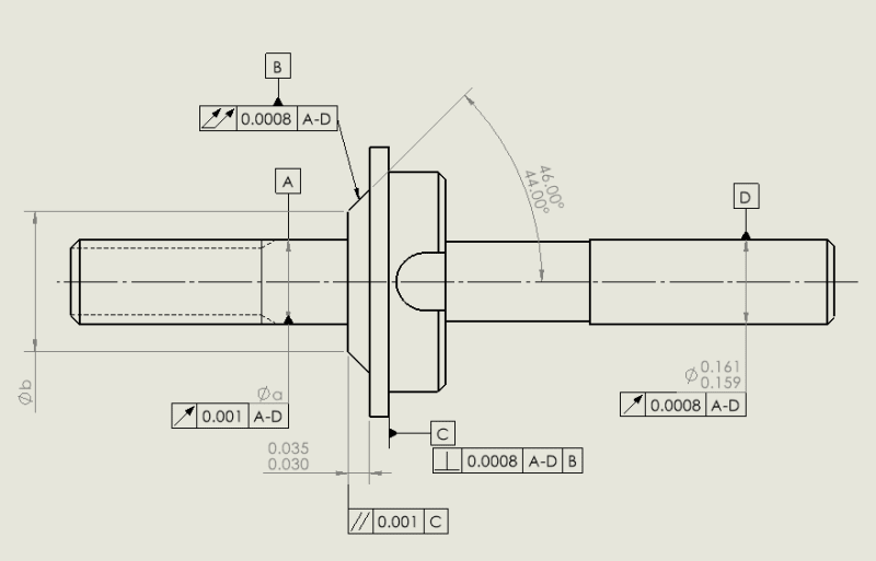
1. Datum features for inspection might differ during machining.

2. The method of holding a part during inspection dictates its allowable movement. For runout and perpendicularity referencing datum A, the part can move axially and rotate. For parallelism with datum B, only rotations are constrained.

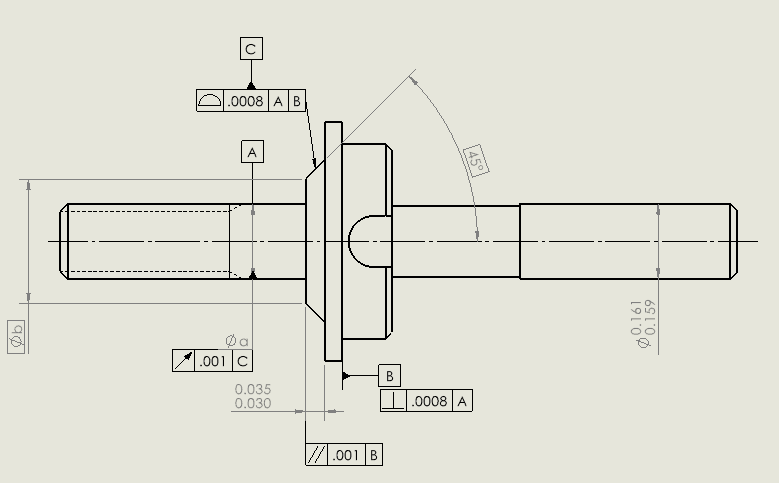
3. The total runout on a cone in relation to datum axis A is comparable to a surface profile tolerance. Using the profile might offer clearer interpretation.

---------------------------------------------------------

Dave,
Unfortunately, I don't have access to the 2018 version yet. We are still stuck in 2009 version. But I will definitely look into 2018 version down the road.

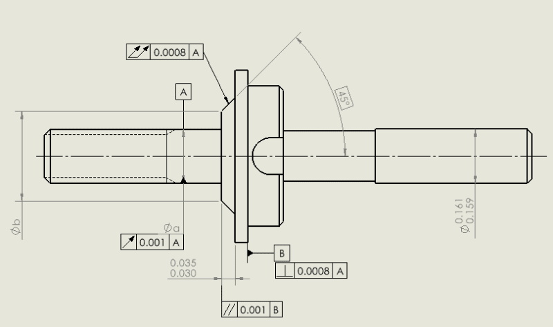
1. The standard lacks a clearly specified tolerance zone for total runout on angled surface and has been a debated.

2. During manufacturing and inspection, parts shouldn't move at all. The absence of a datum reference means no priority. (the inspector would fill any void to completely fix the part, after existing datums on the drawing established) Datum features signify assembly constraints; however, for parts moving axially, an axial constraint on the drawing isn't beneficial.

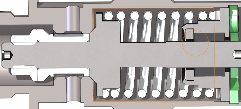
3. Yes, I forgot to show the hidden line, the rod does have pilot holes at the ends.

---------------------------------------------------------------
It looks like both of you would prefer profile over total runout in this case.


Greenimi,

the initial datum D has a clearance fit, there is a bushing guiding datum D, to prevent excessive tilt, which might throw datum B off from the mating surface. I removed it in the second figure because I thought it's not important to part's function, and it might add complexity to the inspection, also didn't want to reject parts due to datum D alone. As far as the part function goes, datum D can even be rectangular if needed, it won't have much impact.
NHA_faknmf.png


New correction based off Burunduk, 3DDAVE and greenimi's feedback:

GD_T_Case_7_zpgssn.png

I can use runout with respect to datum C, right?
I don't have to dimension the distance from datum A axis to the angled surface, right? The standard in this case would assume symmetry between the tapered surface and the datum A axis by default.
 
Honestly I don't like the circular runout to the cone's axis. It is not something I will ever do.
For functional reasons, why cone to datum A is profile and the same relationship is also controlled with the circular runout?

Sprinkling GD&T on the drawing is not really a smart idea.....just saying
 
I agree with greenimi that controlling datum feature A relative to C for runout and then controlling datum feature C back to A as primary for profile can't be right.
Judging by the application, I would consider going back to the common datum A-D established from the two diameters as it was in the initial version, specifying a surface profile tolerance for the cone relative to A-D and labeling it as datum feature B, and then controlling the other geometries relative to a datum reference frame based in A-D primary, B secondary.
For example, the face contacting the spring (currently datum feature B) would get a profile tolerance relative to A-D,B - which would both govern an orientation perpendicular to the common axis and location relative to the cone at the same time (and also the flatness of that surface).
 
greenimi,

Agree on the cone.

rollingcloud,

I don't care for datum feature reference loops. Some feature or feature group positions the part and carries the other features with them. There can be a cascade where one set positions a part in a larger assembly and then the positioned feature(s) form the basis to position the part relative to another item; the potential A->B->C->A dependency loop sucks.

Circular runout is fine as a tolerance refinement. Adding cylindricity or circularity to A, if that is a concern, is also a possible solution; depends on the problem to be solved.

Circular runout on the cone relate to A is another refinement to improve sealing.
 
Just an insight on aftermarket car parts. Controlling a revolution with a single runout. Don't know the OP's precision requirements but I think if it ain't a needle valve it doesn't need too much gd&t.

6420__20307_sentq1.jpg
 
greenimi,
Understood, no datum loop.

Burunduk,
Would profile on the spring platform be an overkill? What do you think about having perpendicularity with respect to the cone?

Dave,
Circular runout on the cone won't control the form/straightness though.

Wuzhee,
Thanks for the example, I see 3 runouts tho.
 
Circular runout is fine as a tolerance refinement, not as a form control and I did not indicate otherwise.

It is far easier to create a seal with a seat that is circular.

Regardless of tolerance a cone will primarily make line contact unless there is deformation or lapping to match, so the sealing will be on a single circle.

One could combine circular runout with profile of line with the latter controlling slope of the cone. Use a basic diameter
on the cone to gauge the location of the cone or locate features relative to it.
 
rollingcloud said:
Would profile on the spring platform be an overkill? What do you think about having perpendicularity with respect to the cone?

Certainly not an overkill. It will locate the face and orient it at the same time, and will spare you from specifying a perpendicularity tolerance and a directly toleranced distance as two separate requirements. If someone thinks that fewer requirements is an overkill compared to more requirements - that should be solved by explanation. Also note that profile is the only way to unambiguously control the location of the face relative to the cone, because your reference will be a datum and the control will use a well-defined tolerance zone.
 
Just a thought... Couldn't the flat face that is perpendicular to datum feature A and is currently controlled with the parallelism tolerance of .001 to B be used as secondary datum feature for this part? Then the cone and the spring platform could be controlled with profile toleranes wrt A|B.
 
pmarc, could you elaborate why you suggest the flat face and not the cone?
In the application, it looks like the cone is the stopper in the axial direction.
 
Status
Not open for further replies.
Back
Top