Continue to Site

Eng-Tips is the largest engineering community on the Internet

Intelligent Work Forums for Engineering Professionals

  • Congratulations GregLocock on being selected by the Eng-Tips community for having the most helpful posts in the forums last week. Way to Go!

Apply concentrated force on reference point to spread out the load on surface 1

Status
Not open for further replies.

bojoka4052

Mechanical
Oct 8, 2021
108
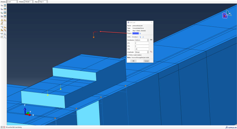
I create tie constraint between the top surface of a solid elements structure, and reference point to which we apply a concentrated load. I want this concentrated load to be spread out over the surface:
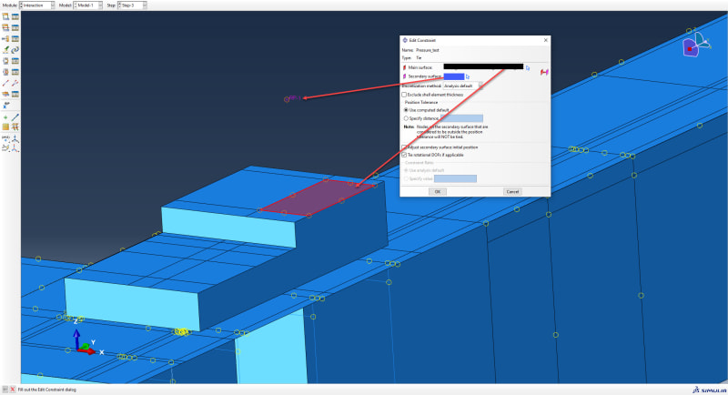
1_g8ykcx.jpg

2_h2l5pn.jpg


When I run the job I get the error: "Too many attempts made for this increment Job XXX: Abaqus/Standard aborted due to errors." Any ideas what might be causing this?
 
Replies continue below

Recommended for you

Don’t use tie constraint for this purpose, it’s not meant for such cases. Use rigid body or kinematic coupling constraint instead.
 
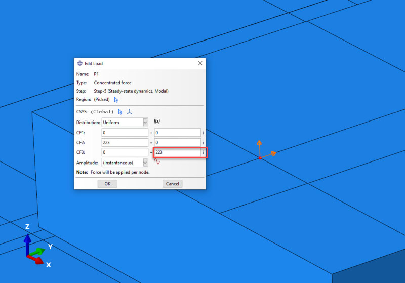
Thank you FEA way, its not related but if I may ask something else about Abaqus. When I am doing a modal analysis, loads are given in terms of their real and imaginary components. The real component will just be a force acting in the Y-direction, but what would the imaginary part be doing?

1_nq1srh.jpg
 
You can specify the value in the "imaginary" field to define the out-of-phase part of the load. Check how harmonic loading is defined in steady-state dynamics analyses.
 
Just last questions FEA way if I may, Ive been reading the documentations;

Do we always need to have an imaginary part? The "imaginary" component defines the out-of-phase part of the load, if all my loads are "in-phase" does this mean I do not add the imaginary part?

What does it mean to be "in-phase"? In phase with the sinusoidal waves caused by the harmonic excitation?
 
You don't have to define it. Actually, in most cases the imaginary part is not used and loads are specified as in-phase which means more or less what you described but the excitation itself is sinusoidal.
 
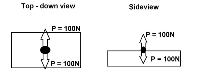
I know I said last question, but I just have to ask one more because I get so much out of it; If this is how the loads Ive been given look like, 100 N (from a rotating mass) acting on an object in four different directions , how would you apply them in Abaqus?

1_poyark.jpg


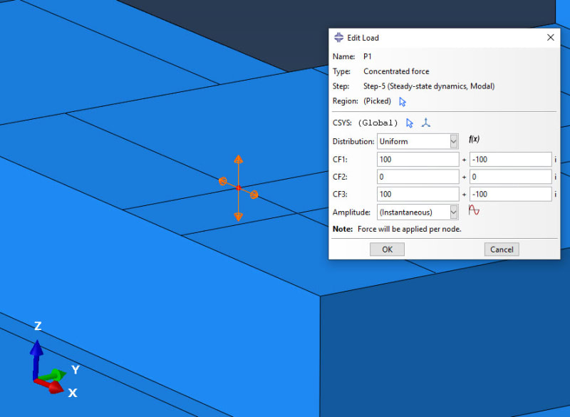
Would this be correct? I am assuming the imaginary component of the load will have as much of an impact on the response as the real component. And since the imaginary part of the load acts in the opposite direction of the real, it will also be out-of-phase, hence making it correct to write it in the right box with the "i" after?
1_hlfkpt.jpg
 
I still wouldn’t use the imaginary loads unless absolutely necessary and just define real ones in each direction. But it all depends on the details of the problem that you want to simulate. If this is some kind of standardized test, you may find guidelines in engineering codes. If it’s a typical loading experienced by a particular type of structure, literature might be helpful.

Not only the direction of loads is important but also how they vary in time with respect to each other.
 
Status
Not open for further replies.

Part and Inventory Search

Sponsor