Continue to Site

Eng-Tips is the largest engineering community on the Internet

Intelligent Work Forums for Engineering Professionals

  • Congratulations SSS148 on being selected by the Eng-Tips community for having the most helpful posts in the forums last week. Way to Go!

Apply torsion on steel member

Status
Not open for further replies.

dccd

Civil/Environmental
Feb 19, 2021
150
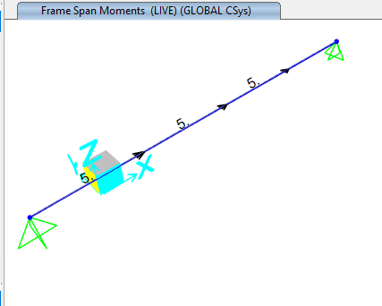
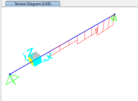
Hi, all. Just wondering which way of assigning point torsion of beam is the correct way ? I am using SAP2000 . The member is 5m, with point torsion at 1.25m, 2.5m and 3.75m respectively. In the first diagram, I assign the point torsion on frame directly (There's no joint along the member). Here's the torsion diagram looks like.

torsion_1_-1_rwombi.png

torsion_1_-2_uh8xk2.png


In the second way, put points in SAP2000 @ 0m , 1.25, 2.5, 3.75m and 5m. After which I draw the member and assign the point torsion to the point direcctly. Here's the torsion diagram looks like...

torsion_2-1_fokor2.png

torsion_2-2_xrmtcd.png

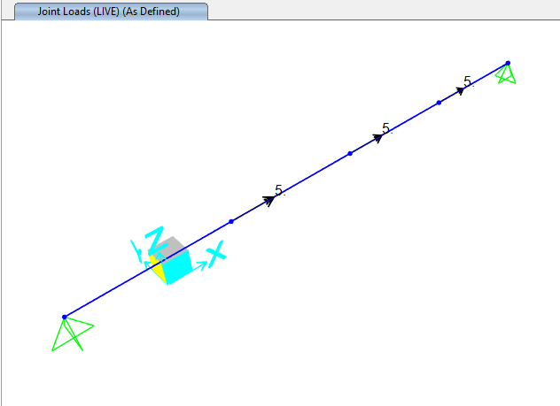
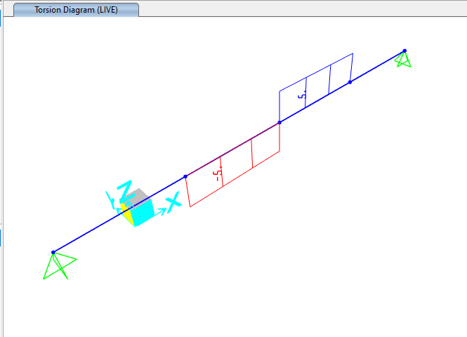
I have applied torsion as moment about x-axis. Which is the correct way ? Can someone enlighten me ??
 
Replies continue below

Recommended for you

The two methods should do the same thing. Check your models as they should give the same results with the same boundary conditions. Clearly they don't so something isn't right? First result looks correct for one end restrained against twist and the other not. Not sure what's going on in the second set of screenshots. Possibly I'll conditioned model? Are you sure you're restraining the member from spinning?
 

Both can be correct acc. to modelling and load directions..

- The first one, the left support free to rotate around X axis while the right support resisting the torsional loading. The torsional loads applied at 1.25m, 2.5m and 3.75m at negative direction.. ( if you look from left to right, counter clockwise direction..

- The second one, the beam subdivided and frame local axises do not coincide with global axis and you define the load for local axis..Moreover, the beam at 2.5m , is loaded with 10 unit of torsion ( not 5)..

I will suggest you to study the tutorials and worked examples..
 
Either way should work fine.

I do like the idea of modeling it both ways to compare the results. Then investigate the results if you see any differences.
 
HTURKAK said:
- The second one, the beam subdivided and frame local axises do not coincide with global axis and you define the load for local axis..Moreover, the beam at 2.5m , is loaded with 10 unit of torsion ( not 5)..


I have problem of unsderstanding the 2nd method, I have assigned 5 unit of torsion in the same direction at 1.25m ,2.5m and 3.75m respectively. Why the torsion somehow become -10 unit at 2.5m location?

0001_xe220e.jpg
 
dccd ...I have problem of unsderstanding the 2nd method said:
I have assigned 5 unit of torsion in the same direction[/b] at 1.25m ,2.5m and 3.75m respectively. Why the torsion somehow become -10 unit at 2.5m location?]

You did not define the same direction!!!..
Just look to the member no's , and sequence of relevant joint no's you will see.... 2nd and 3rd elements local axis will not coincide with global positif directions ..

Apparently, your claim is, the computer never does quite what you want ..but only what you tell it ???..If this is the point ,I fully agree with you.. you are right.

These crazy machines and softwares just do what ever we tell rather than what exactly we want...


HTURKAK said:
You did not define the same direction!!!..
Just look to the member no's , and sequence of relevant joint no's you will see.... 2nd and 2rd elements local axis do not coincide with global positif directions ..

Apparently, your claim is, the computer never does quite what you want ..but only what you tell it ???..If this is the point ,I agree with you.. you are fully right.

These crazy machines and softwares just do what ever we tell rather than what exactly we want...

I have checked thru the model , it seems that the model is unstable , error popping up when I finished running the analysis. Just wondering why the model is unstable ? It's pinned pinned at both side, why it would become unstable ?
Perhaps the instability of the model leading to the weird torsion diagram ??
0002_yz3tge.jpg
 
Check the restraint to the member spinning like I mentioned in the first post I made. Restrain the rotation about the X axis at one end. Ensure there are no pins in the member.
 
Agent666 said:
Check the restraint to the member spinning like I mentioned in the first post I made. Restrain the rotation about the X axis at one end. Ensure there are no pins in the member.

So, I have restrained rotation about x at one end , the torsional diagram somehow become correct now.

Just wondering in the first method, why I dont have to restrain teh roation about x at one end? While for the second method, I have to restraint the rotation at one end ?

0003_y9veyq.jpg
 
Well you should have to restrain the X axis rotation in both scenarios, otherwise both are unstable in the same way. Check the log of the first method and see if it contains any insight, like errors, etc.

The issue with etabs/sap is that sometimes even though the analysis is fundamentally incorrect or unstable, it still gives you a plausible answer in some situations and you can be fooled. It relies on you as the design engineer to check and interpret the analysis logs and decide its all garbage or all good.
 
Agent666 said:
Well you should have to restrain the X axis rotation in both scenarios, otherwise both are unstable in the same way. Check the log of the first method and see if it contains any insight, like errors, etc.

The issue with etabs/sap is that sometimes even though the analysis is fundamentally incorrect or unstable, it still gives you a plausible answer in some situations and you can be fooled. It relies on you as the design engineer to check and interpret the analysis logs and decide its all garbage or all good.

Thanks for pointing out. In the first method, I have checked thru the log . Ya, it's unstable. So, I have assigned fixed rotation about x axis in one of the member end. Viola, the torsion diagram is still the same, and no error popiing up.

Btw, can you suggest any good SAP tutorial books to read ? I found that the SAP tutorial that comes with the program not really helpful.
 
I'm not aware of any books specific to Sap2000 beyond the manuals which are fairly useful. These can be found in the install directory.

The CSI wiki is also a fairly useful online resource.
 
Status
Not open for further replies.

Part and Inventory Search

Sponsor