Continue to Site

Eng-Tips is the largest engineering community on the Internet

Intelligent Work Forums for Engineering Professionals

  • Congratulations SSS148 on being selected by the Eng-Tips community for having the most helpful posts in the forums last week. Way to Go!

ARBITRARY WAVEFORM DEFINITION

Status
Not open for further replies.

MRSSPOCK

Mechanical
Aug 29, 2010
303
I wonder can anyone please help me understand the defining of arbitrary waveforms, using something like for example a Sigilent SDG1020.

I am thinking of buying this SDG1020, so I have trawled around a bit but can't find the answer I'm looking for.

I'm curious if, for example, lets say I have a portion of a captured wave that I want to use as a part of my arbitrary wave, is there some feature that would let me capture a portion of the said wave with an oscilloscope, then transfer this captured portion into the arbitrary waveform generator, where I can then edit it down to very portion that I want use?

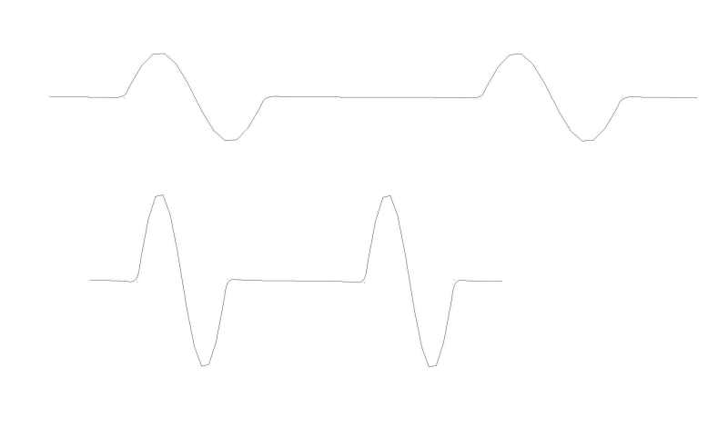
My aim is to capture the pulse from an ignition's magnetic pickup using a scope, then transfer this pulse to an AWG so that I can use the AWG as an engine speed simulator.

I realise that a simple sinewave could be used, (along with a dead period to represent the time delay between pickup pulses), to mimic the engine pickups output, but I am just curious as to whether these AWG or any AWG machines will let me capture a real wave in a scope, then use this as the basis for my arbitrary wave.

I intend buying a scope also, so the description above doesn't relate to a specific scope, since I haven't bought it yet either. Any advice in that regard might also be useful.

This is purely a hobby based purpose, so I obviously don't want to fork out a huge amount, but don't mind spending £400 or £500 for both of the above in total.

Thanks
 
Replies continue below

Recommended for you

Thanks for the link.

The first point is that the following statement sounds reassuring,

[highlight #8AE234]"Tools to create and edit waveforms as well as import data created outside the tools"[/highlight]

yet when I download both the following pdf's and search the entire documents for the word "import", the word isn't found. I was trying to see what import formats it could read.


But even more worrying is the following statement,

[highlight #8AE234]" and the ability to switch almost instantly between two frequencies, the arbitrary/function generator (AFG) is the right tool. "
[/highlight]
which would suggest it is not possible to simply compress or expand the wave along the horizontal axis, by simply turning a knob.


Since my plan is for an engine pulse simulation, the ability to quickly "rev up" is very important to me.

So thanks again for that link, which seems to indicate the AWG would not actually provide me with the options I am looking for.

I wonder is that true for all AWG's, i.e. that they would not let me "rev" my engine simulator via a knob?

It doesn't seem to be a very complicated feature to include. I am surprised since it seems such a fundamental feature?

Thanks
 
Near as I can tell from the documentation and from the software, the only viable option is CSV formatted file data. You could probably run your captured data into a CSV file and edit as desired and input that into the EasyWave software.

TTFN
I can do absolutely anything. I'm an expert!
faq731-376 forum1529
 
Thanks for your replies, but I have just realised that the AWG won't actually work for another reason.

I forgot to take into account that the pickups sinusoidal output increases in amplitude with engine rpm.

I don't believe any AWG could be programmed to mimic that feature, such that the amplitude would increase with frequency increase.

Maybe I will just start a new thread to see if anyone can recommend a simple analogue circuit that might let me produce such a waveform.

Thanks again.
 
"...an ignition's magnetic pickup..."

Could you just use a zero crossing detector?


Sure, it can. You can program it with mathematical functions, or you can use Excel to create digitized versions of the equations, if the program can't do them. All you need is some sort of plausible formula.

TTFN
I can do absolutely anything. I'm an expert!
faq731-376 forum1529
 
I just rang Siglent and asked the question directly.

Apparently there is no way to replicate what I want directly from the AWG, without having it hooked up to a PC and running a program live from the PC.

Does anyone know an alternative device which can carry out the frequency variation, with amplitude varying simaultaneously, as a function of frequency?

All I want is something that can sweep from the first image to the second image, by the turn of a knob.

Thanks
sinewaves_h5rzwk.jpg
 
Use a permanent magnet motor spinning a toothed disk. Place the pickup in proximity to the disk. Power the PM motor with a variable DC power supply. Vary the voltage to the PM motor.

Bill
--------------------
"Why not the best?"
Jimmy Carter
 
@waross Thanks, but I already have that set up.

I prefer the idea of having more flexibility and less mechanical hardware.

It's not so easy getting a motor that can rotate steadily at 200rpm, which can also rev up to 16000rpm

It's quite a range to accommodate.

I realise there are ways to achieve it mechanically, but I prefer not to go down that route, since

soon it becomes almost as simple to just use a real engine, which obviously defeats the purpose of creating a simulator.
 
Thanks for the kind reply and explanation.
You may try a one-shot on a sine wave to give a pulse at the start of each cycle. A capacitor in series with your signal may attenuate the lower frequencies. Alternately a Zener diode to clip the peaks. I doubt that your software is looking for an exact wave form. It is just looking for pulses and may be easy to fool.
If this will work, you need to find a variable frequency waveform generator and use sine waves.
200-16000 RPM is a turn-down ration of 80-1. The automotive software is most likely clipping the higher voltage developed at higher frequencies.


Bill
--------------------
"Why not the best?"
Jimmy Carter
 
Yes, with an arduino. Preporgram it with a shape function that is voltage dependent, and a frequency output that is voltage dependent.

So, you've got a pot, and you want an output peak voltage proportional to frequency then something like

signal_out=V_pot*sin(V_pot*time)*mark_space_function(time,V_pot)

is the sort of thing.

Cheers

Greg Locock


New here? Try reading these, they might help FAQ731-376
 
@GregLocock I like the sound of that idea. I must have ago once I get my head around how to execute it. Thanks
 
Status
Not open for further replies.

Part and Inventory Search

Sponsor