Continue to Site

Eng-Tips is the largest engineering community on the Internet

Intelligent Work Forums for Engineering Professionals

  • Congratulations KootK on being selected by the Eng-Tips community for having the most helpful posts in the forums last week. Way to Go!

Arm and disc mechanism forces

Status
Not open for further replies.

C98hris

Mechanical
Oct 11, 2013
5
Hi,

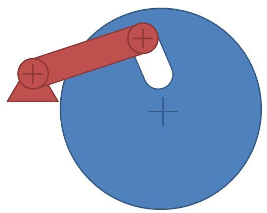
I have a mechanism with a disc that has a slot in it. An arm is connected to the slot with a sliding connection. The arm is held at one end with a fixed pivot position. When the disc rotates the arm can move up and down within the slot and its angular position is related to the angular rotation of the disc. Images are below.

I have two questions that I am struggling with:
1. If I apply a torque to rotate the disc how do I calculate the force that is applied to the arm
2. Is there an optimum design of the slot which maximizes the force transfer (curved, straight, 45° to arm axis etc..)

Thanks
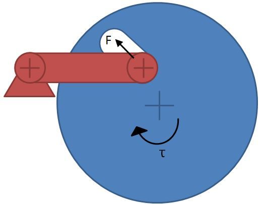
down_qykitv.jpg


up_ryjsmz.jpg
 
Replies continue below

Recommended for you

1. The force will be what is needed to overcome any forces opposing the arm motion. As drawn, 0.
2. No. 100% of the force will always be "transferred".
 
Hi

I'm not sure that your disc and lever will work as drawn, it appears you have a very small angular movement of the disc and I can't see how the disc would drive the link pin to the top of the slot.

“Do not worry about your problems with mathematics, I assure you mine are far greater.” Albert Einstein
 
Start with these assumptions:

If the follower inside the slot is free sliding or rolling, the force applied to the follower is acting normal to the slot surface, and located at the point of contact.

Also, the reaction force at the fixed pivot will always be directly in line with the arm.

Draw some vectors and do a little trigonometry and you'll be on your way.
 
Forget the existence of the disk.
It's a cam and follower problem, with a very unfortunate ramp.


Mike Halloran
Pembroke Pines, FL, USA
 
C98hris said:
1. If I apply a torque to rotate the disc how do I calculate the force that is applied to the arm
2. Is there an optimum design of the slot which maximizes the force transfer (curved, straight, 45° to arm axis etc..)

1) If you assume both radii big enough, you have a roller forced to climb an inclined plane that slides from left to right. Then, draw a free-body diagram and calculate the forces perpendicular to each radius.

2) Since Work = Torque x Angular velocity, the slot in the disc that produces the biggest torque on the oscillating follower with roller is the one that induces the slowest constant angular velocity of the arm or radial velocity within the disc.

"God will not look you over for medals, degrees or diplomas, but for scars." - Elbert Hubbard
 
I would slightly curve the slot to ensure rotation otherwise the system will probably bind or lock up. In order to investigate your models make it out of cardboard.
 
I agree that it would likely lock up without a curvature to the slot. Though it does have 1 DOF.
I would draw the kinematic vectors and then inversely solve for the forces.
 
2. An increasing spiral groove will give more force outward. One full revolution of the disc for the desired outward movement of the arm. The required torque will also be lower.

Ted
 
as drawn the disc can rotate only a small amount

another day in paradise, or is paradise one day closer ?
 
As drawn, yes. The question ask if a different shape would generate more force. That seems to imply that rotation may not be limited, only the motion of the arm is limited.

Ted
 
Status
Not open for further replies.

Part and Inventory Search

Sponsor