Settingsun
Structural
I’m trying to decode the strength of welded aluminium members to AS/NZS 1664-1997. The section that deals with this is only two pages so I’ve posted it. I don’t find it clear but it seems to me that the standard is based on the specification (code) in the (US) Aluminum Association’s Design Manual (AADM) which is better presented (IMO) and has a proper commentary. My office has the 2010 edition of AADM so not the same edition as when the AS/NZS was written. Reading the AADM helps but I’m still not sure whether the AS has been intentionally varied (or the AADM has changed since the AS was written) or whether any apparent differences are just down to the general lack of clarity of the AS with the intention being the same as AADM.
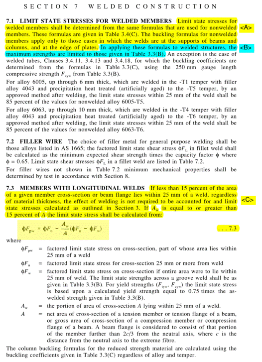
My first question is whether using the much-clearer AADM provisions for welded members would comply with AS 1664. AADM always gives welded member strength as a function of non-welded and fully-welded member capacity. These could be calculated according to AS 1664, then use the AADM interpolation. The rest of my questions on items <A> to <E> go away if that’s the case.
Also, I assume you treat members that have localised welding such as cleats as longitudinally-welded since only part of the cross-section is weld-affected. This may be conservative for overall member capacity as the welding isn't full-length, just at discrete locations, but there doesn't seem to be any other provisions.
Referring to the parts of AS 1664 identified in the images:
<A> The first sentence says to use the same formulas as for non-welded members. The third sentence places a limitation on use of the non-welded buckling formulas but doesn’t give an alternative for cases that fall outside the limitation. Is this just a double-up of the requirements set out in Clause 7.4 for transversely-welded members, or is this somehow meant to apply to longitudinally-welded members also?
<B> “In applying these formulas…”
Is this referring to all formulas in Table 3.4(C), or just the buckling formulas?
<B again> “the maximum strengths are limited to those given in Table 3.3(B).”
Table 3.3(B) gives the minimum mechanical properties for welded alloys which are often much lower than for non-welded. However, Clause 7.3 gives two cases for longitudinally-welded members: either no reduction due to welding if the weld-affected area is small; or a capacity that falls between that for a non-welded member and that for a member that is entirely weld-affected. Both of these are more than the stress limit from Table 3.3(B), so what is the intention of this limit in Sentence <B>? Is it missing a reference to the weld-affected zone, ie only the weld-affected zone is subject to this limitation on strength?
<C> Just highlighted for comparison with <B>, and to note that it is the same (re-arranged) formula as used several times in AADM for welded members.
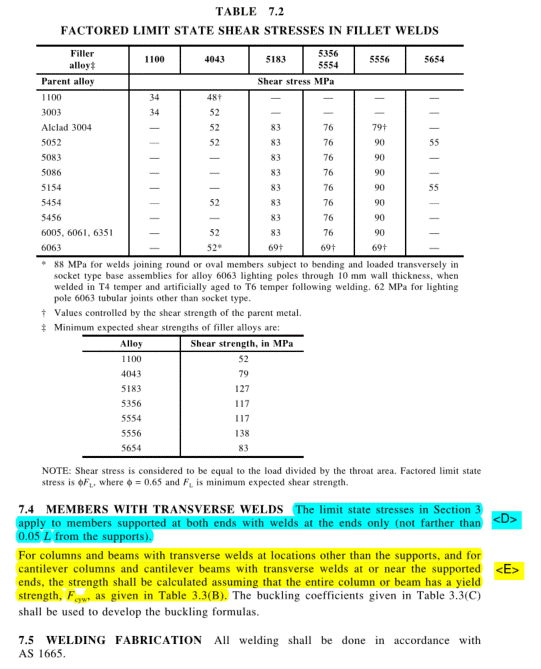
<D> Based on AADM, I think that welds at the “ends only” refers to welds near supports (restraints to buckling), so a continuous bending/compression member with a mid-length splice near an interior support still qualifies even if the weld isn’t at the end of the overall continuous member. Ie “end” means end of span. Thoughts?
<D again> Is this another case where the stress limit can exceed the limit set out in <B>? Really not sure what <B> is getting at unless it applies to only the weld-affected zone.
<E> Tension members aren’t covered by this part nor by <D> [IMO. I think <D> is aimed at column/beam buckling.] This may tally with AADM which has different rules for transverse welds in tension members: no reduction in gross-section yield strength due to transverse weld; transverse weld strength is based on weld-affected *tensile* strength instead of weld-affected yield strength. But I don’t think AS 1664 spells out how to handle welds in tension members. Thoughts?


