Continue to Site

Eng-Tips is the largest engineering community on the Internet

Intelligent Work Forums for Engineering Professionals

  • Congratulations KootK on being selected by the Eng-Tips community for having the most helpful posts in the forums last week. Way to Go!

AS4041 Piping Design

Bengie47

Mechanical
Dec 16, 2024
3
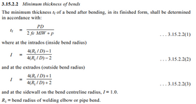
When comparing AS4041 and ASME B31.3, I noticed a difference between the way they handle minimum wall thickness calculations for bent pipes.

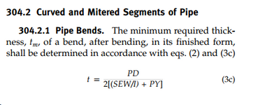
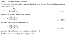
Compare the formulas in the following sections;
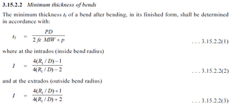
AS4041 Cl. 3.15.2
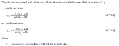
ASME B31.3 Cl. 304.2

AS4041 suggests a larger wall thickness is required in the extrados of the bend
ASME B31.3 suggests a larger wall thickness required in the intrados of the bend

FEA of some sample geometry showed higher stresses in the intrados, suggesting to me that the ASME approach is correct.

Further, it was not clear to me how to best use these calculated tf values and how they interacted with the formulas 3.15.2.2(4) and (5).
Are these formulas just suggestions for starting points to then be refined through prototyping, in order to satisfy the calculated tf value?
When instead using the ASME approach for tf (which seems more correct), we have found that bending straight pipe with starting thickness of tf will satisfy this formula.
ie. the intrados thickness increases and extrados thickness decreases.

With this being the case, it seems these formulas largely do not constrain the design, and instead calculating the straight pipe value gives the same result.
Is it only relevant in the case of different manufacturing methods, eg. welding two halves together to achieve a uniform thickness bend - I can see in this case the bent pipe formula would govern.

Does anyone have experience with these clauses, and able to provide any insight - is there something I am missing here?

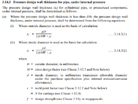
I also had a question about AS4041 3.14.3(1) and (2) - it is not clear under what circumstances one uses one formula over the other.
Do you pick whichever best suits your manufacturing needs, whichever one gives you the best result? How to determine the "basis for calculation"?
 
Replies continue below

Recommended for you

I just had a look, and I'm thinking that the Australian Commitee copied the formula wrong :S, I have come across that before in some obscure clauses.

From a fundamental point of view, the basis of these calcs is that a pipe will try and "straighten out" when subject to internal pressure, and as a result more stress is put on the intrados, and hence the introdos has to be thicker. If you think about the same pressure being applied, there is more area on the extrados, so a force imbalance exists. sounds like your FEA model showed the same thing.

In practice the only time I have used these calcs is a quick and dirty assessment of wear on an elbows in service, to try and justify an extra mm or 2 of erosion allowance. Most manufacturers of induction bends will qualify a batch of bends by doing destructive testing on at least manufactured elbow, rather than rely on just this simplified calcs.

for 3.41.3 (1) vs (2) they should give almost the same, if not the same answer. If you derive the hoop stress calculation from scratch, and then used the Tresca failure approach, you should end up the same equation. In practice for piping, I've only every known anyone to use the outside diameter approach.

For 3.15.2.2(4) and (5), tb is the recommended thickness of a straight pipe, before you start bending it, during bending is stretches and becomes thinner. it's just a guide so that you don't start with a pipe just on the limits, then bend it and it is now too thin to use.

I think i answered everything, might be a bit jumbled in order, but couldn't be bothered to re-write its the end of the day :)
 
Bengie,

A note for the future - there are very few people here who will know or have copies of Australian codes, so this time or next time, please copy in the relevant wording / formula so that those of us who could comment, but don't have the AS code can do so.
 
I just had a look, and I'm thinking that the Australian Commitee copied the formula wrong :S, I have come across that before in some obscure clauses.

From a fundamental point of view, the basis of these calcs is that a pipe will try and "straighten out" when subject to internal pressure, and as a result more stress is put on the intrados, and hence the introdos has to be thicker. If you think about the same pressure being applied, there is more area on the extrados, so a force imbalance exists. sounds like your FEA model showed the same thing.

In practice the only time I have used these calcs is a quick and dirty assessment of wear on an elbows in service, to try and justify an extra mm or 2 of erosion allowance. Most manufacturers of induction bends will qualify a batch of bends by doing destructive testing on at least manufactured elbow, rather than rely on just this simplified calcs.

for 3.41.3 (1) vs (2) they should give almost the same, if not the same answer. If you derive the hoop stress calculation from scratch, and then used the Tresca failure approach, you should end up the same equation. In practice for piping, I've only every known anyone to use the outside diameter approach.

For 3.15.2.2(4) and (5), tb is the recommended thickness of a straight pipe, before you start bending it, during bending is stretches and becomes thinner. it's just a guide so that you don't start with a pipe just on the limits, then bend it and it is now too thin to use.

I think i answered everything, might be a bit jumbled in order, but couldn't be bothered to re-write its the end of the day :)

Thank you for your detailed response, much appreciated.

for 3.41.3 (1) vs (2) they should give almost the same, if not the same answer.
In my cases I tend to find using the inside diameter results in a smaller tf value result. For some cases, using outside diameter results in a tf > d/4, where if I change to use the inside diameter formula it falls below this value.

For 3.15.2.2(4) and (5), tb is the recommended thickness of a straight pipe, before you start bending it, during bending is stretches and becomes thinner. it's just a guide so that you don't start with a pipe just on the limits, then bend it and it is now too thin to use.
We have found that bending the pipes will become thinner at the extrados, but actually thicker at the intrados. I wonder if this is manufacturing method dependent.

But for example, if we start with a pipe of thickness "x", the bent pipe formulas would then require min thickness "x+" at intrados (using ASME approach) and "x-" at extrados. Our samples show that when "x" is set to the straight pipe calculated tf, this would also satisfy the bent pipe calculated values. So as far as I can tell, essentially the bent pipe formulas place no additional constraint on the design (in my case at least). Am I still missing something?

This is assuming I can ignore the 3.15.2.2(4) and (5) tb values as just "recommendations" and not requirements.
 
Bengie,

A note for the future - there are very few people here who will know or have copies of Australian codes, so this time or next time, please copy in the relevant wording / formula so that those of us who could comment, but don't have the AS code can do so.
Thanks for the tip, I will try to add in the specific references here.


Screenshot 2024-12-18 072039.png


Screenshot 2024-12-18 072207.png

Screenshot 2024-12-18 072320.png
 

Part and Inventory Search

Sponsor