Hi all
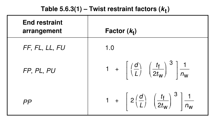
A question about the application and determining the k_t factor from table 5.6.3(1) of AS4100 or NZS3404, just something I was wondering if anyone else had come up against this scenario, and how you may have treated it?:-
Brief background to the question, writing a few python scripts to assess some steel code requirements and this kind of thing always gets me thinking about some of the fringe cases to ensure the programming logic treats them appropriately.
This particular case is something I've never really thought of previously. It isn't based on some real situation. Mostly theoretical I guess if this scenario ever came up in real design (possibly continuous crane runway beams is one real world example).
Consider the case of a monosymmetric beam member segment with end restraints combination such that k_t does not equal 1.0, with reversing moment and inflection point somewhere out in the span with no other intermediate restraints. t_f in the two equations is defined as the critical flange thickness. With the reversing moment diagram, both bottom and top flanges are the critical compression flanges at some point in the segments span. So which flange thickness to use in the equations for k_t?

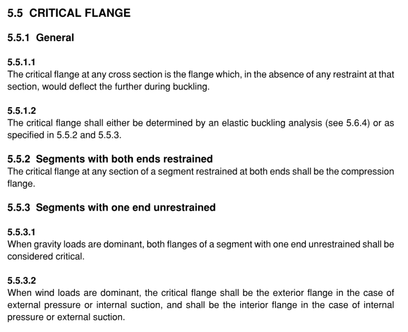
Strictly speaking codes refer to critical flange in section 5.5 as that which deflects furthest, appreciate we could do a buckling analysis for our loading/restraint scenario to get the end answer directly that would take account of the end capacity in this scenario, or at the least confirm which flange is the critical one for the segment based on the greatest deflection criteria. The definition in 5.52 doesn't help us here.

For purposes of my python script I'd probably just take the first point below and use this conservative answer (nice and easy, well aware doing anything else is probably over thinking things). But I could see for cases where most of the segment length has the critical flange being the smaller thickness flange that there must be some benefit that might be able to be taken account of if another method exists without having to do a rational buckling analysis to prove this.
1. Just take the most conservative value based on thickest flange. i.e. k_t is largest for most conservative effective length (L_e).
2. Some other formulation, rule, working from first principles, other known equation, weighted average, etc? Basically I don't know, hence the question!
Don't believe I've ever seen anything discussing this particular aspect, so reaching out for any thoughts/references/etc?
Thanks for any replies!
A question about the application and determining the k_t factor from table 5.6.3(1) of AS4100 or NZS3404, just something I was wondering if anyone else had come up against this scenario, and how you may have treated it?:-
Brief background to the question, writing a few python scripts to assess some steel code requirements and this kind of thing always gets me thinking about some of the fringe cases to ensure the programming logic treats them appropriately.
This particular case is something I've never really thought of previously. It isn't based on some real situation. Mostly theoretical I guess if this scenario ever came up in real design (possibly continuous crane runway beams is one real world example).
Consider the case of a monosymmetric beam member segment with end restraints combination such that k_t does not equal 1.0, with reversing moment and inflection point somewhere out in the span with no other intermediate restraints. t_f in the two equations is defined as the critical flange thickness. With the reversing moment diagram, both bottom and top flanges are the critical compression flanges at some point in the segments span. So which flange thickness to use in the equations for k_t?

Strictly speaking codes refer to critical flange in section 5.5 as that which deflects furthest, appreciate we could do a buckling analysis for our loading/restraint scenario to get the end answer directly that would take account of the end capacity in this scenario, or at the least confirm which flange is the critical one for the segment based on the greatest deflection criteria. The definition in 5.52 doesn't help us here.

For purposes of my python script I'd probably just take the first point below and use this conservative answer (nice and easy, well aware doing anything else is probably over thinking things). But I could see for cases where most of the segment length has the critical flange being the smaller thickness flange that there must be some benefit that might be able to be taken account of if another method exists without having to do a rational buckling analysis to prove this.
1. Just take the most conservative value based on thickest flange. i.e. k_t is largest for most conservative effective length (L_e).
2. Some other formulation, rule, working from first principles, other known equation, weighted average, etc? Basically I don't know, hence the question!
Don't believe I've ever seen anything discussing this particular aspect, so reaching out for any thoughts/references/etc?
Thanks for any replies!


