Eng-Tips is the largest engineering community on the Internet

Intelligent Work Forums for Engineering Professionals

AS4100 - Weld design for fabricated welded column

Status
Not open for further replies.

li0ngalahad

Structural
May 10, 2013
86
0
0
AU
Hi everyone,
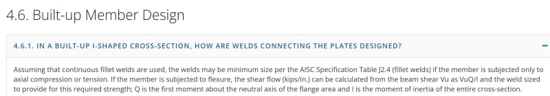
If we need to design a welded column, subject to axial load, how do we determine the design loads for the welds connecting the flanges to the web?

I know for a beam that is subject to shear and bending moment, the weld is designed using the shear flow, f=VQ/I, and it's easy enough to find the design load for the weld as I usually have a clearly defined shear V*, or in alternative, we can just design the weld based on the web's full shear capacity. However, for a column that is not subject to significant shears, doing so would be overly conservative.

So my question is, how would we approach this when we do not have a clear shear force to design to? One idea I have is to design the weld based on 2.5% of each flange plate section capacity in compression, making sure I develop enough force to prevent its out-of-plane buckling - for example, if my flange plate has a section capacity of 1000 kN and a maximum unrestrained height of 300mm before the plate "member" capacity starts being influenced by buckling and becomes lower than the section capacity, I design a weld that can take 250 kN every 300mm of length, for example, 2 x 6CFW SP 125/175 HIT/MISS.
I would do this for both flanges and also for the web (although the web will rarely govern the design as it will have double welds and it has usually a smaller section area than the flanges)

Any thoughts on this? Is there any code provision taht can help with this (could not find any)?
Thanks
 
Replies continue below

Recommended for you

I agree with what you proposed, i.e. treat each flange as its own member and design the welds for the 2.5% restraint force.

You could check out AS 5100.6 Clause 10.4.1, which is intended for laced/battened compression members, but specifies a minimum shear force for the column to be designed to. I would think it would be applicable to your case also.
 
I think that the 2.5% approach is a poor approach with any rational basis. Buckling is a predominantly stiffness phenomenon not a strength phenomenon. Sure the code says 2.5% but that doesn't make it the correct value, especially when you are dealing with what is effectively a very stiff connection.

Also I presume that your 250kN value was a typo as that is 25% not 2.5%.

Really this is more about ensuring there is a robust and more than sufficient capacity for suitable shear flow. Gusmurr's suggestion sounds like a good start.
 
gusmurr
Thanks for the tip on AS5100, will chack that out

human909
Yeah I agree the code approach to restriant is not the best and buckiling in reality is based on stiffness, nonetheless the 2.5% approach is generally used with buckling restraint of members based on the code, and I was trying to find some code-based way to design these welds. Will check the AS5100 clause suggested by gusmurr
And yes, that was definitly a typo - I meant to write 10000 kN capacity, not 1000.
 
From the AISC website...

Clipboard01_msecky.jpg


-----*****-----
So strange to see the singularity approaching while the entire planet is rapidly turning into a hellscape. -John Coates

-Dik
 
I think you are correct that the strength criterion is the one to look at here. Welds are enormously stiff and the stiffness requirement will surely be satisfied. The only way the weld can fail to provide restraint to buckling is if it has insufficient strength.

The required restraint force becomes smaller as stiffness increases, approaching a minimum requirement asymptotically.

20230204_215755_bb75lo.jpg


Added: don't max out your b/t ratio because there must be some reduction in local buckling capacity at the flange tip due to non-continuous restraint at the web. Surely not theoretically correct, but using diagonal distance for 'b' might be an adequate shortcut.
 
I've never seen a PEMB column with intermittent welds for column sections.

-----*****-----
So strange to see the singularity approaching while the entire planet is rapidly turning into a hellscape. -John Coates

-Dik
 
dik said:
I've never seen a PEMB column with intermittent welds for column sections.
Nor have I but that doesn't mean that it shouldn't be considered... Also expect that PEMB would suitable describe this AS4100 structure. Unless I misundstand the meaning of PEMB.

I'd hazard a guess that intermittent welds are less likely to be used for welded column sections because engineers are fundamentally cautious and conservative and not always the ones bearing the cost of designing welded columns.

Labour in Australia is pretty damn expensive so considering intermittent welds might seem suitable.
 
human... you don't think that if it were a reasonable solution that PEMB manufacturers would be doing it. It's possible for automatic welding 'machines' to do intermittent welds. Based on past experience your caution would not be applicable to PEMB fabricators. If they could 'safely' do it, they would. If there were fatigue issues, they would likely have a 'check box' on their computer program that would provide continuous welds.

-----*****-----
So strange to see the singularity approaching while the entire planet is rapidly turning into a hellscape. -John Coates

-Dik
 
It's interesting to speculate on why something isn't done, but maybe their welds tend to be optimised anyway. I'm sure I've read about welds only on one side of the column-flange interface to avoid flipping the member during fabrication. Maybe by the time the section is slimmed down to minimum dimensions (increasing shear flow), only welding one side, and using a 3mm weld, there's nothing left to cut out.

A smaller continuous weld should be cheaper than an equivalent (larger) intermittent weld, so intermittent would only be considered if you're at the minimum permitted weld size.
 
dik said:
human... you don't think that if it were a reasonable solution that PEMB manufacturers would be doing it.
Like said in the past and suggested here, the PEMB world of North America is one that doesn't exist in the same form in Australia. At least that is my understanding. (We do seem to have a pretty cut throat PEMB market of the cold formed steel variety.)

With a different design environment, different labour costs, different fabrication setups and different codes the economics are not directly comparable.

As far as I'm concerned I avoid welded columns and beams due to their very high cost. I've certainly seen other engineers use them naively without regard for their cost.
 
Status
Not open for further replies.
Back
Top