HDStructural
Structural
Hello All,
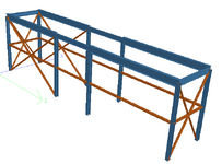
I am working on a design for an elevated vessel and am designing a support structure for it. The structure will look something similar to the attached image. The seismic base shear from the equipment is about 45% of the wind base shear, so wind controls but there are seismic requirements that need to be followed.

The structure is SDC D and the state uses ASCE 7-10. My question has to do with one of the requirements in 15.7.10.4.
This section states "The connection of the post or leg with the foundation shall be designed to resist both the vertical and lateral resultant from the yield load in the bracing assuming the direction of the lateral load is oriented to produce the maximum lateral shear at the post to foundation interface."
Is this essentially saying that I need to design my anchor bolts for the "yield" load in the braces, which would be the tensile capacity.
It can't mean compressive capacity since it would state buckling load or something.
I expected that I would have to design these connections considering the seismic load with the overstrength factor applied, but I am not seeing that. Designing for the yield load would result in brace forces of 100k, compared to a 30k C or T brace force from wind and a 14k brace force from seismic (35k with overstrength). Designing for 100k seems excessive.
I am working on a design for an elevated vessel and am designing a support structure for it. The structure will look something similar to the attached image. The seismic base shear from the equipment is about 45% of the wind base shear, so wind controls but there are seismic requirements that need to be followed.

The structure is SDC D and the state uses ASCE 7-10. My question has to do with one of the requirements in 15.7.10.4.
This section states "The connection of the post or leg with the foundation shall be designed to resist both the vertical and lateral resultant from the yield load in the bracing assuming the direction of the lateral load is oriented to produce the maximum lateral shear at the post to foundation interface."
Is this essentially saying that I need to design my anchor bolts for the "yield" load in the braces, which would be the tensile capacity.
It can't mean compressive capacity since it would state buckling load or something.
I expected that I would have to design these connections considering the seismic load with the overstrength factor applied, but I am not seeing that. Designing for the yield load would result in brace forces of 100k, compared to a 30k C or T brace force from wind and a 14k brace force from seismic (35k with overstrength). Designing for 100k seems excessive.
