Follows on from thread378-436363.
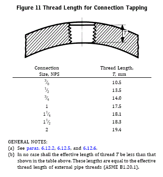
I am trying to interpret exactly what is being said in Figure #11 (attached). Nothing in Interpretations 1 through 4. Assume we are looking at the face of a flange and drilling a tangential hole that would go between bolt holes. 2 colleagues thought this was the wall of a pipe - as I initially thought. It does not make sense when the hole size goes up to NPS 2". Clause 6.12.2 states "Holes may be tapped in the wall of a fitting if the metal is thick enough to allow the effective thread length specified in Figure 11."
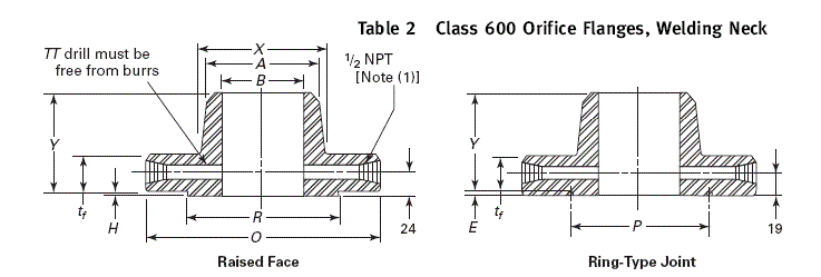
I have previously used ASME B16.36 - Orifice Flanges when asked for guidance on drilling tangential holes in flanges. This is limited to a 1/2" hole.
Thank you for any help


