Navigation
Install the app
How to install the app on iOS
Follow along with the video below to see how to install our site as a web app on your home screen.
Note: This feature may not be available in some browsers.
More options
Style variation
-
Congratulations MintJulep on being selected by the Eng-Tips community for having the most helpful posts in the forums last week. Way to Go!
You are using an out of date browser. It may not display this or other websites correctly.
You should upgrade or use an alternative browser.
You should upgrade or use an alternative browser.
ASME B31.1 weld type question 2
- Thread starter xjboonie
- Start date
- Status
- Not open for further replies.
-
1
- #2
Not sure, but fluid eleastic vibrations will eventually rip the plate off and it will plug downstream equipment. Initial crack will be from thermal stress, and vibrations will complete the failure. Several famous accidents were caused by similar constructions ( eg, LMFBR ).
"...when logic, and proportion, have fallen, sloppy dead..." Grace Slick
"...when logic, and proportion, have fallen, sloppy dead..." Grace Slick
Boonie
If we can assume that your device is meant to modify flow within a steam system, why do it this way ?
Are there no steam valves available in the area where you live ?...... New or used ???
Cheapest solution would be an RO contained within a new set of flanges ???.... Perhaps ?
Steam systems do not operate the same way as liquid systems ....
MJCronin
Sr. Process Engineer
Dhurjati Sen
Materials
double sided fillet weld
DHURJATI SEN
Kolkata, India
DHURJATI SEN
Kolkata, India
The original post said it was complete joint penetration, so it can't be a double fillet weld. Fillet weld must be fused to the root, but they are not required to penetrate beyond the root into the joint.
I don't believe the post was asking whether the weld is a fillet or a groove weld, but whether it was circumferential or longitudinal or girth, etc. Circumferential and girth welds are typically butt joint. This application appears to be simply a groove welded T-joint with reinforcing fillet welds using AWS terminology. Still, I don't think that was the real question in the original post.
Best regards - Al
- Thread starter
- #8
can you provide any specifics on those accidents?davefitz said:Several famous accidents were caused by similar constructions ( eg, LMFBR ).
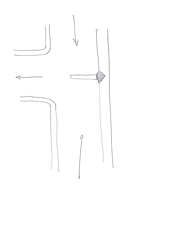
yes, it is to straighten steam flow and reduce pressure fluctuations. This is one tee in a header with 3 inlets and 2 outlets. It is an existing system.MJCronin said:If we can assume that your device is meant to modify flow within a steam system, why do it this way ?
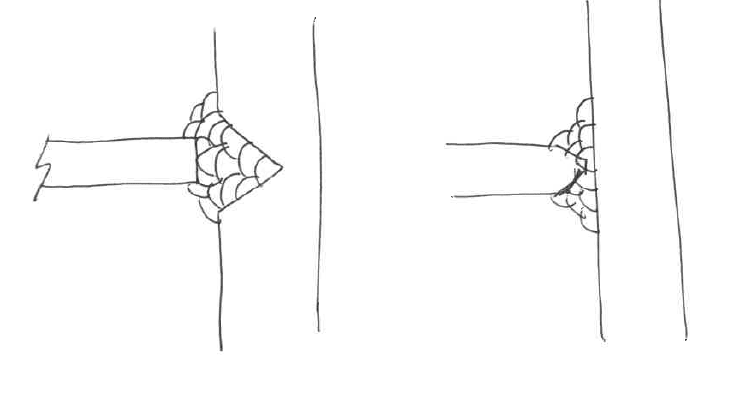
that's my bad on the sketch part - the plate is prepped with a double bevel grind, while the interior of the tee is just cleaned up. My poor attempt to show the full penetration weld.KevinNZ said:Putting the weld prep in to the wall of the tee does not seem right. Why not prep the edges of the plate?
yes, it is to straighten steam flow and reduce pressure fluctuations.
Does anybody else out there in "eng-tips" land buy this ??
No, Steam does not act that way... The piece you describe will not "straighten flow" or reduce pressure fluctuations.
How do you know that your flow is not straight ?
What are the steam operating pressures and temperatures ? What is your steam velocity at the tee and is it within normally accepted limits ?
MJCronin
Sr. Process Engineer
-
1
- #10
KevinNZ:
the Fermi I LMFBR had a failure caused by a fluid distribution plate break free and plug a liquid sodium cooling channel. Likewise the Monju LMFBR had a sodium coolant leakage failure when a thermocouple cracked at a partial penetration weld and broke free due to fluid induced vibrations. In both cases the initial crack was due to thermal stress, and high cycle fatigue from fluid-elastic vibrations led to complete failure.
More common is the failure of fossil fuel power plant spray attemporators, usually interstage attemporators between the 2 final superheaters. Both the spray nozzles and the header liners are vulnerable to thermal shock cracking if they are manufactured of stainless steel. The correct design that does not fail is to use inconel or P91 nozzles and liners , and the liner should be kinetically formed to the header ID ( "detna formed") using explosive detenation cords.
For the monju thermocouple, a full penetration weld would have extended its fatigue life by a factor of at least 20.
One systemic problem with major power engineering desings is the lack of awareness of the issues related to thermal stress, fatigue , and fluid elastic vibrations. Exactly zero colleges on the planet called earth teach these areas during undergraduate studies, and thus the design engineers are clueless until after failure of the part and then read the forensic metallurgical analysis .
"...when logic, and proportion, have fallen, sloppy dead..." Grace Slick
Amen,....davefitz.....
I have been involved with the design, analysis, specification and testing of steam and other high energy systems for over 40 years
I have never seen such an internal device on a steam piping system before ......
MJCronin
Sr. Process Engineer
I have been involved with the design, analysis, specification and testing of steam and other high energy systems for over 40 years
I have never seen such an internal device on a steam piping system before ......
MJCronin
Sr. Process Engineer
- Status
- Not open for further replies.
Similar threads
- Replies
- 0
- Views
- 1K
- Replies
- 0
- Views
- 474
- Replies
- 6
- Views
- 14K
- Replies
- 1
- Views
- 9K
- Replies
- 2
- Views
- 807


