Continue to Site

Eng-Tips is the largest engineering community on the Internet

Intelligent Work Forums for Engineering Professionals

  • Congratulations IDS on being selected by the Eng-Tips community for having the most helpful posts in the forums last week. Way to Go!

ASME B31.3 vs Sec VIII Div I Weld 1

Status
Not open for further replies.

ehbadger

Chemical
Oct 7, 2015
119
This question is related to this one here (I can delete that one if this violates the crosspost rules, I have a slightly different question now so I am leaving them both for the moment)
Link

Anyway, short and sweet review. Getting some tantalum lined pipe made. Its 18" DIA, 150# flanges, etc for process piping in a chem plant. My state (KY) is a code state and so we are expected to follow ASME B31.3 for process piping. The question came up on a double miter elbow, are partial (incomplete) penetration welds acceptable? (Doing a full-pen weld is very difficult with the Tantalum liner).

Everything I found in 31.3 indicates that basically, no, they are not. I heard back from the vendor this morning that the partial pen welds called out on their drawing are "acceptable and calculated / designed per ASME Sec VIII div I" and that "Spot RT" is not required at all.

So my question is, Is that allowed? Does designing a weld per Sec VIII Div I override/comply with B31.3? Are there any code-mandated inspections?

I have a copy of B31.3 handy but not Sec VIII Div I. I don't mind looking at it in detail if someone just wants to point me to the right section/table/whatever. Any help is much appreciated. Thanks

 
Replies continue below

Recommended for you

ehbadger;
No. First, one cannot cheery pick applicable sections of other code books to try to ensure compliance. If B31.3 is indeed the code of construction and you are required to follow it, you cannot refer to another code book section unless it is referenced.

With regard to Section VIII, Div 1 vessel construction, partial penetration welds are acceptable for corner joints - see UW-12.
 
Thanks so much for the help! Ok, so you stated that
metengr said:
If B31.3 is indeed the code of construction and you are required to follow it, you cannot refer to another code book section unless it is referenced.

Looking through B31, 323.4.3(d) states:
(d) Fabrication by welding of clad or lined piping components and the inspection and testing of such components shall be done in accordance with applicable provisions of the BPV Code, Section VIII, Division 1, UCL-30 through UCL-52, or the provisions of Chapters V and VI of this Code, whichever are more stringent.

So I take this as B31.3 referencing SecVIII DivI as a valid design path (provided Chapter V and VI of 31.3 aren't more stringent). Is the UW-12 you mentioned within Sec VIII Div I UCL-30 through UCL-52?

Are miter joints @ 45deg considered a "corner joint"? Again, sorry if this is obvious in SectVIII I just don't have a copy handy right now.

Thanks
 
So, since Section VIII, Div 1 is indeed referenced, now you have a means to evaluate use.
The reference to UCL-30 to UCL-52 is for clad vessels.

See the applicable reference for clad vessels in ASME Section Div 1 below for your review;

UCL-31 JOINTS IN INTEGRAL OR WELD METAL
OVERLAY CLADDING AND APPLIED
LININGS
(a) The types of joints and welding procedure used shall
be such as to minimize the formation of brittle weld composition
by the mixture of metals of corrosion resistant alloy
and the base material.
(b) When a shell, head, or other pressure part is welded
to form a corner joint, as in Figure UW-13.2, the weld shall
be made between the base materials either by removing
the clad material prior to welding the joint or by using
weld procedures that will assure the base materials are
fused.
The corrosion resistance of the joint may be provided
by using corrosion resistant and compatible weld filler
material or may be restored by any other appropriate
means.

I have not seen the design nor applicability but having reviewed the above and B31.3, I don't consider miter joints corner joints, so they must be completely fused.
 
B31.1 assumes the welds a full pen for the stress analysis. If they are partial welds then a higher SIF is required.
 
KevinNZ, thanks for the comment

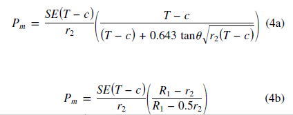
What I have learned now is that the vendor performed the B31.3 calculations 304.2.3 using the depth of the weld as the pipe wall thickness.

However there is no SIF (assuming you mean stress intensification factor) in the equations. Or would this be the quality factor "E" from Table A1-B?
Capture_cqxyh9.png


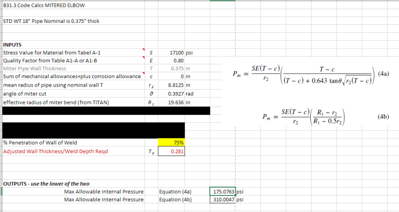
Here is my spreadsheet calculator I threw together to run the calcs. Not sure how to incorporate a "SIF"
Capture222_kqxznu.png


From my results it looks like a partial penetration weld of 75% of the pipe wall (nominal 0.375", so 75% is 0.281" thick) is the minimum thickness required to meet the design pressure (175psi). Does that seem correct?
 
Here is an excerpt from Table A-1A

*The quality factors for castings Ec in Table A-1A are basic
factors in accordance with para. 302.3.3(b). The quality
factors for longitudinal weld joints Ej in Table A-1B are basic
factors in accordance with para. 302.3.4(a). See paras.
302.3.3(c) and 302.3.4(b) for enhancement of quality
factors. See also para. 302.3.1(a), footnote 1.

The above E is a casting quality factor OR

302.3.4 Weld Joint Quality Factor, Ej
(a) Basic Quality Factors. The weld joint quality factors,
Ej, tabulated in Table A-1B are basic factors for
straight or spiral (helical seam) welded joints for
pressure-containing components as shown in
Table 302.3.4.

In either case, this has nothing to do with what is being proposed as some kind of knock down factor for inadequate penetration for miter. Second, you can't mix and match Piping Codes. If SIF is not addressed in B31.3, it is not addressed.
 
Thanks metengr. I will ignore SIF. I did not see it anywhere in B31.3 either.

I am planning to allow the vendor to proceed with the partial penetration weld, but incorporating NDE (UT) spot checks during fabrication to ensure we are achieving the required weld depth of (0.281") or 75% of pipe wall thickness. This seems to satisfy B31.3. Would you agree?

 
ehbadger;
Here is the problem I have with this approach. A miter weld joint with partial penetration welds is like leaving a pre-existing flaw where local primary and bending stresses can result in fatigue crack propagation in service. I don't like this type of approach when it comes to mitered branch connections. These should be full penetration welds.
 
metengr, thanks again. Are you aware of any tools available to evaluate that, or would that require some sort of FEA? We have CESAR stress analysis kit but I don't think that gets as specific as weld details on an individual piece.. got a meeting with the resident guru on Monday for that already.

Apparently the fabricator has been doing it this way for years and years and never had an issue. And frankly no one has ever caught it. I spoke to another vendor who also does it this way, with just some extra weld passes on the exterior of the partial pen seam. So relevant experience indicates it shouldn't be an issue. But I'd really like to prove it out one way or the other.

At this point I am just pursuing it for my own curiosity since I don't have a clear answer yet.. don't know if I am opening a can of worms or not, we will see! [upsidedown]
 
ehbadger;
Here is my take. There are topics not covered in the Code because either they have been acceptable or are deemed insignificant. I am sure the design offered by the vendor can be pencil whipped into acceptance because of the assumption that you have sufficient wall thickness to retain internal pressure despite a miter weld with IP (incomplete penetration). If I was purchasing a double miter elbow knowing that besides internal pressure, the elbow will experience thermal/mechanical stresses, I would specify full pen welds. But, that is me.
 
ehbadger,
This was my original response,
If you want to comply with B31.3 it must be full penetration - end of story.
The only reference to partial penetration in B31.3 is

328.7 Attachment Welds
Structural attachments may be made by complete penetration,
partial penetration, or fillet welds.

However, I found this that may or may not help

Interpretation 23-02
Subject: ASME 831.3-2008, Table 341.3.2, Partial Joint Penetration Welds
Date Issued: April 23, 2010
File: 10-534
Question: Does para. 300(c)(3) allow partial joint penetration welds if a more rigorous analysis
addressing the design, construction, examination, inspection, and testing details is documented
in the engineering design and accepted by the owner?
Reply: Yes. Note that requirements for Code rules that are not applicable as written to such
construction, such as examination and fatigue design, need to be addressed. See also Interpretation
16-12.

Interpretation: 16-12
Subject: ASME B31.3a-1996 Addenda. Para. 3OO(c)(3), Intent of the Code
Date Issued: November 10. 1997
File: B31-97-026B
Question (I): Maya piping designer use para. 3OO(c)(3) of ASME B31.3a-1996 Addenda and apply a
more rigorous analysis to qualify the design and acceptance criteria 0f piping where the Code requirements
employ a simplified approach?
Reply (I): Yes. if the designer can demonstrate the validity of the approach to the owner.
Question (2): In accordance with ASME B31.3-1996 Edition. does a piping system that has been designed
in accordance with the Code but not fabricated or assembled as specified by the engineering design, comply
with the Code if a more rigorous analysis proves it suitable for the service intended?
Reply (2): No. See para. 300.2. Definitions - Assembly and Erection. Also, see para. 341.3.2.

Regards,
DD
 
Status
Not open for further replies.

Part and Inventory Search

Sponsor