Continue to Site

Eng-Tips is the largest engineering community on the Internet

Intelligent Work Forums for Engineering Professionals

  • Congratulations IDS on being selected by the Eng-Tips community for having the most helpful posts in the forums last week. Way to Go!

ASME-FEA: Peak stresses

Status
Not open for further replies.

Alekos91

Mechanical
Jan 28, 2016
7
Hello,

I run a FEM analysis with ANSYS Workbench on a steel thin disk-plate (please see pic.)
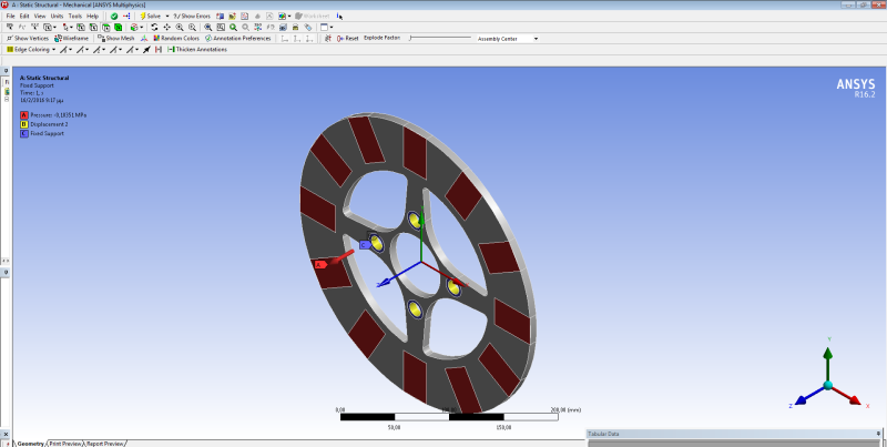
Thin_steel_disk_k7zs8k.png
. The check for the structural integrity of the disk is according to ASME codes Sec.VIII div 2 Part 5 (I assumed the codes could be applied even if my component is not a pressure vessel...), but I am not sure if I followed the right procedure. I looked at some past threads at the forum, but I didn't get a clear answer at my questions. So:

I ran an elastic analysis and made the stress intensity linearization at the cross section with the highest Stress Intensity. I found the membrane(M) and membrane+bending(M+B) stresses and they are found to be lower than the limits of 1S and 1.5S referred to ASME codes Sec.VIII div 2, 5.2.2. So I checked that my cross section is OK regarding plastic collapse. I also calculated the sum of the 3 principal stresses and it is lower than the 4S limit refered to (5.3.2). So the disk passes the local failure check.

However, through the stress linearization I observed that I have some peak stresses extended at a tiny area (1.8 % of thickness) at the upper and lower surfaces of the disk and with their value up to about 2S. What should I 'do' with these peak stresses if my load is static and therefore a fatigue analysis has no meaning..?

Moreover,if I run a elastic-plastic analysis, the ASME codes Sec.VIII div 2, 5.2.4 suggests the use of a factored load, but I do not understand the criterion for verifying that a location at my disk will not collapse through plasticity. What exactly does the 'non-convergence' of analysis mean?

Thanks a lot!
 
Replies continue below

Recommended for you

A few comments:

You need to satisfy the limits in 5.2.2 everywhere - the location of highest equivalent stress (you are using von Mises, and not Tresca, right?) may not necessarily be the location of highest local membrane stress. Your geometry would not have any general membrane stress.

For a Division 2 pressure vessel, a fatigue analysis is required if the fatigue screening assessment in 5.5.2 does not pass. If your load is purely static and does not cycle, then you can likely pass the fatigue screening, exempting your component from a fatigue analysis. However, the ratcheting requirements in 5.5.6 or 5.5.7 is required nevertheless.

As far as the elastic-plastic analysis goes, do you understand how you factor the loads and also model the full elastic-plastic true stress-true strain curve from 3-D? If your analysis converges to a statically-permissible solution, then your analysis converges. The opposite is non-convergence - I agree that the terminology is awkward - the Code Committee is working to fix that.
 
Hi TGS4,

Yes I am using von Misses stress to find the 'most dangerous' cross section and actually I do the stress linearization for more than one 'dangerous' cross sections. The evaluated membrane stresses (local or general) are under the limits of the code at any section.

As for ratcheting, the Division 2 at 5.12 defines ratcheting as 'produced by a sustained load acting over the full cross section of a component, in combination with a strain controlled cyclic load or temperature distribution that is alternately applied and removed.'. Since I have not a cyclic load, how can I make a ratcheting check?

As for the elastic-plastic analysis, what I understand from 'load-factors' is that I have to give to ANSYS a bigger load, i.e. 2.4 bigger and after giving the stress-strain curve of the material (extended till the ultimate tensile strength) to ANSYS , I run the analysis and wait to see if I will get a result. If I get a result, it means that I have a statically-permissible solution under this bigger load and the disc will not fail through plasticity under the actual load. If I do not get a result from ANSYS, it means that the disc cannot withstand the ACTUAL load -not the bigger one. Is that right? But what if convergence is not managed due to insufficient memory for example...? Is there such a case?
 
The rules of Part 5 require the ratchet check, regardless of the number of operational cycles.

Your understanding is generally correct re elastic-plastic. If you don't converge because of something unrelated to the physics of the problem, that's not "real", is it?
 
First of all thank you for your answers.

After your last post, the question seems to be in which way can someone check if the unconvergence is due to a numerical cause or a physical one?

Moreover, should I change the convergence settings of the FEM programe (here ANSYS) so that I make the convergence more easy or difficult to happen?

I say that because I tried to run an elastic-plastic analysis with a different model (different shape of disc) at which is ''obvious with the eye'' (I know it is not the most appropriate/scientific term) that the disc will have at least some local plastic failure. However, I got a result (the analysis converged) and the local failure criteria was also fulfilled. So, I wonder if I have to put a lower ''convergence criterion'' at ANSYS's ''Analysis settings''...?

I hope I did not confuse anyone..
 
If your model is set up correctly, then there ought to be no difference between a numerical or physical cause. Your example of a memory issue is neither numerical nor physical. Your engineering judgement would apply to determine the specifics, nevertheless.

Convergence criteria for non-linear analyses basically consists of setting the minimum increment size for a Newton-Raphson iteration approach. An arc-length or Riks Method approach should be avoided, although the rules in VIII-2 Part 5 do not prohibit that specifically. Tweaking the convergence criteria (making the minimum increment size larger or smaller) shouldn't generally affect the final result.

Note that for Division 2 construction, there is a different design margin/load factor for Local Failure, and for that failure mode, convergence is not a criteria.

Note that local and gross plasticity will occur at the factored loads, and is generally anticipated. It is the load redistribution as the tangent modulus decreases (and eventually becomes zero at the true ultimate stress) that dictates whether or not the solution converges to a statically-permissible solution.
 
Status
Not open for further replies.

Part and Inventory Search

Sponsor