Eng-Tips is the largest engineering community on the Internet

Intelligent Work Forums for Engineering Professionals

ASME PTB_3 Example Problem 5.5.4 (Elastic-Plastic stress ) Twice-Yield Method

Status
Not open for further replies.

Pro_west

Automotive
Mar 25, 2024
4
0
0
CA
Hello All

I have a question regarding ASME PTB_3 Example Problem 5.5.4 (Elastic-Plastic stress Analysis):

***
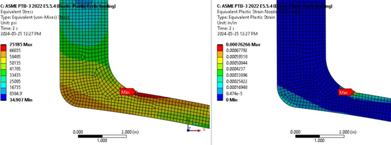
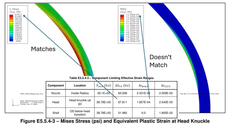
In Table E5.5.4-3 the values of Equivalent stress and plastic strain range doesn't match with the Figures E.5.5.4-2 and 5.5.4-3.

Am I missing something here? How the values of Equivalent stress and plastic strain range are different in Figure and Table.

***

Thanks in advance.
 
Replies continue below

Recommended for you

The example deals with the areas in the model which presents the highest Δεeff,k values.
Δεeff,k is function of ΔSp,k & Δεpeq,k, the locations with the highest Δεeff,k values in the model will not necessarily be those with the highest equivalent stress (ΔSp,k) or the highest equivalent plastic strain range (Δεpeq,k) in the model.

I hope it make sense.
 
Thank you @IdanPV for pointing out a very good point to me.

However, if you see following table. The Table E5.5.4-3 is taking a lower value of Δεeff,k.

ASME_jrwefy.jpg


I created a FEA model and can confirm the location of ΔSp,k & Δεpeq,k is same as given in the Figure E5.5.4-2 (See below).


ASME_1_k5hfml.jpg


So, if the highest value of Δεeff,k are of interest, then ASME shouldn't have used the values given in Figure Figure E5.5.4-2?
 
See STEP 5 of the example.
The areas of interest are the nozzle inside radius, head knuckle , and the shell.
The maximum values of ΔSp,k & Δεpeq,k which can be seen in Figure E5.5.4-2 does produce higher Δεeff,k value but does not occur in the nozzle inside radius.
 
The Figure E.5.4-1 shows the overall value of ΔSp,k & Δεpeq.

Figure E.5.4-1 shows ΔSp,k & Δεpeq at nozzle inside radius which is also the maximum values.

Even If we agree the Figure E5.5.4-2 is not for the nozzle inside radius. ASME should have considered the maximum ΔSp,k & Δεpeq value (from Figure E.5.4-1) for the overall fatigue life calculation. Since that would be most conservative life. However, I do not see anywhere in the Table E5.5.4-3 that most coderivative case has been used.
 
ASME PTB-3 said:
"The effective strain range was calculated for multiple points in each area to ensure that the maximum (limiting) strain range was analyzed"

Figure E5.5.4-1 shows the von-Mises stress and the equivalent plastic strain of the entire model but only 3 locations within the model was analyzed: the nozzle inside radius, head knuckle , and the shell.

Figure E5.5.4-2 shows ΔSp,k & Δεpeq at nozzle inner radius, there are other areas in this figure which shows higher ΔSp,k & Δεpeq value, but those area has not been analyzed in the example as they are out of the area of interest.
 
Figure E5.5.4-3 shows result specifically for head knuckle.

The ΔSp,k value matches however Δεpeq doesn't match at Head Knuckle (ID).

ASME_2_k189ww.jpg


What is the explanation here for no match between Table E5.5.4-3 and Figure E5.5.4-3 for plastic strain of head knuckle ID.

**I can confirm from my FEA that both ΔSp,k & Δεpeq are at same location**
 
The value of ΔSp,k in the head knuckle is 67.811ksi, that is clear and can be seen on the figure by the red color which meets the legend.
The Δεpeq in that location (where ΔSp,k=67.811ksi) is not 2.5e-04 since the legend shows it has a green color which matches the legend.

 
Status
Not open for further replies.
Back
Top