Continue to Site

Eng-Tips is the largest engineering community on the Internet

Intelligent Work Forums for Engineering Professionals

  • Congratulations IDS on being selected by the Eng-Tips community for having the most helpful posts in the forums last week. Way to Go!

ASME Sec VIII Div 1, Allow stresses UG-23(e)

Status
Not open for further replies.

GD_P

Structural
Apr 6, 2018
128
Hello Forum,

We are designing a pressure vessel as per ASME Sec VIII Div 1. For one of the part which is neither standard nor there exist design & construction requirements for such parts in this div, hence we have to use the U-2(g) to comply with this div. Please refer below image which nearly represent the part design concept. The part is purely under bending due to pressure load. As per the FEA results, the bending stresses are very low and are within the allowable tensile stress limits as given in Sec II part D except the notch portion as shown in the picture. For this notch, can we use the higher allowable stress as per UG-23(e) i.e., localized discontinuity stress as 3 times allow stress? Although it seems to be a perfect corner at notch, there will be suitable fillet rad & same is already modelled during the FEA as well.
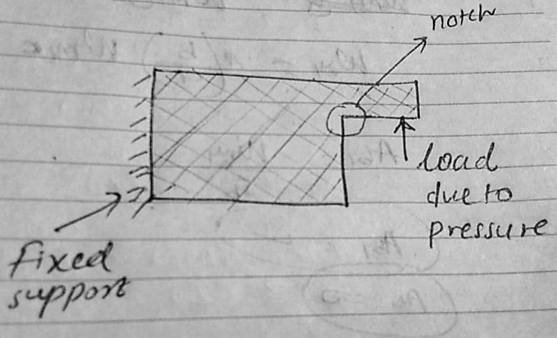
IMG_20191226_225732678_3_a1imgc.jpg


Do share your opinion.

GD_P
 
Replies continue below

Recommended for you

If you're using U-2(g), please follow the instructions in Appendix 46. It will tell you how to handle that.
 
Hi GD_P.
It seems like the high stress you see in the notch is a consequence of singularity of this point - sharp corner.
Try to use small fillet radius in this corner.
You may find this article helpful: There are a lot of examples regarding this issue here:
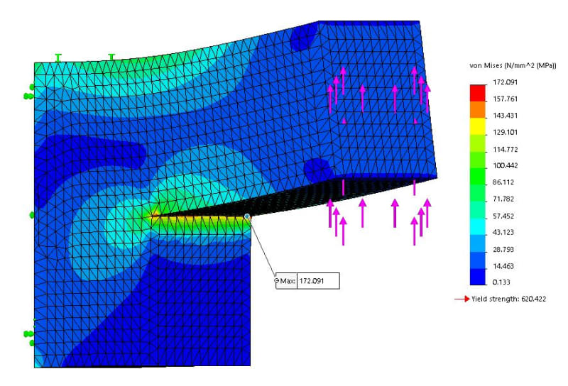
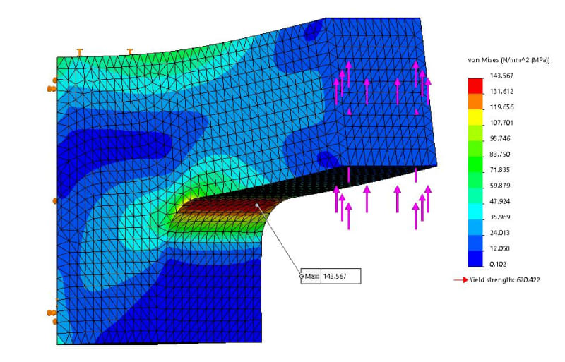
In addition, I made a small example - same boundary conditions and mesh size.
Model with sharp edge, stresses go to infinity.
Cornner_qlt6hn.jpg

Model with fillet radius, stresses has converged
Radius_cdnct9.jpg
 
Thank you TGS4 & IdeaPV for your response.

@TGS4,
You are right, 2019 code edition has introduced appendix 46. This may be helpful, but honestly speaking I am a layman as far as Div 2 is concerned. Also if you see the image of concept design & loading, it very basic bending problem & there is no need to introduce the FEA. The only reason to introduce the FEA was to evaluate the notch stresses (which are known as Localized discontinuity stress IMO, correct me if I am wrong). After analysis I am using the allowable stress as per UG-23, isn't this procedure adequate as per Div 1? I am just trying to avoid the extra efforts , which may be required if we introduce Div 2, please correct me if I am wrong.

@IdeaPV,
I really admire your efforts to clarify doubt. The links are very helpful and I have already informed to our FEA personal a out this topic.

Thank you...

GD_P
 
You don't need to do FEA to use Div 2. Hand calcs are often sufficient, as in your situation.

I'm pointing you in that direction to get a better understanding of the rationale behind the different "limits". You ought to understand those, regardless of whether you do FEA or not.
 
@GD_P,

If you are about to design a Section VIII-1 vessel and you are going to use U-2(g) and FEA in accordance with Section VIII-2 Part 5 you have to use Mandatory Appendix 46 (App. 46, 46-4(c)(1))

For your example, just choose which kind of FEA you want (and can) to apply and then, you need to analysis your results in accordance with the relevant paragraph from App.46 and VIII-2 Part 5.
 
Protection against Plastic Collapse requires that the hand calculated M+B < 1.5xS.

Does local failure at the notch need to be considered?
Using hand calculations, if M+B < 4xS then is local failure protected against?

This would mean that for this geometry, Plastic Collapse occurs before Local Failure?
 
DriveMeNuts - it means that there are different design margins against the two completely different failure mechanisms.

Indeed - all failure modes (with their separate and unique design margins) need to be considered.
 
Status
Not open for further replies.

Part and Inventory Search

Sponsor