Hello,
Below are I attached Figures 4.15.3 and 4.15.4 on this thread for convenience. My question is as to what specifically the shaded areas are referring to (stiffening ring or saddle foot) since the figures are not very specific in the labeling.
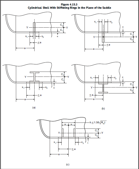
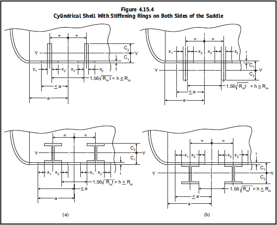
I am performing saddle support calculations and need to determine whether or not the stiffening ring used is considered to be in the plane of the saddle or on both sides of the saddle. I am beginning to think that Figure 4.15.4 (Stiffening rings on both sides of the saddle) is referring to having two separate rings on each side of the saddle support. If so I believe that would make the stiffening ring used on the vessel I am looking at as being on the same plane of the saddle since there is only one stiffening ring on each saddle support.
Can anyone please clarify these figures to me and help me identify which criteria the stiffening rings used in the vessel I am looking at would fall under?
Thanks in advance!!
Below are I attached Figures 4.15.3 and 4.15.4 on this thread for convenience. My question is as to what specifically the shaded areas are referring to (stiffening ring or saddle foot) since the figures are not very specific in the labeling.
I am performing saddle support calculations and need to determine whether or not the stiffening ring used is considered to be in the plane of the saddle or on both sides of the saddle. I am beginning to think that Figure 4.15.4 (Stiffening rings on both sides of the saddle) is referring to having two separate rings on each side of the saddle support. If so I believe that would make the stiffening ring used on the vessel I am looking at as being on the same plane of the saddle since there is only one stiffening ring on each saddle support.
Can anyone please clarify these figures to me and help me identify which criteria the stiffening rings used in the vessel I am looking at would fall under?
Thanks in advance!!