Continue to Site

Eng-Tips is the largest engineering community on the Internet

Intelligent Work Forums for Engineering Professionals

  • Congratulations IDS on being selected by the Eng-Tips community for having the most helpful posts in the forums last week. Way to Go!

ASME VIII-1 | App. 2 or App. Y type determination

Status
Not open for further replies.

XL83NL

Mechanical
Mar 3, 2011
3,056
Hi guys, I'm reviewing a vessel design (VIII-1) and was hoping to get some assistance/back-check on something I cant seem to get my head around. Couldn't find any related older topics ..

A female threaded nut (pos 3) is used to push an insert (pos 8) on the shell (pos 1). The sealing is achieved by an O-ring (pos 4) between pos 1 and 8. The shell also has straight threads that mate with the nut, indicated in red.
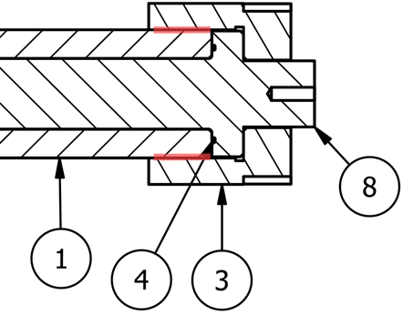
VIII-1_app.what_xzsa2c.png

I'm not overly familiar with app Y, but understand from the scope that App Y is for flanges that have metal-to-metal contact outside the bolt circle. Considering the threads as my 'bolt circle', I'm thinking this design doesn't satisfy that condition of metal-to-metal contact outside the bcd. This more seems like a loose flange type design, e.g. per figure 2-4 (1), since the nut acts as a flange pressing the insert (a lap) to the counterpart.

Any thoughts or confirmation this should be considered a loose type flange per fig 2-4 (1)?

Huub
- You never get what you expect, you only get what you inspect.
 
Replies continue below

Recommended for you

XL83NL, this looks to me like one of those things that don't neatly fit the rules.

I'd say that to try to force it into Apx Y is a needless complication without gaining appreciable accuracy. I think your characterization as a loose flange and lap is closer.

It might even be appropriate to just design per good engineering practice, that is, ordinary strengths-of-material.

Regards,

Mike

The problem with sloppy work is that the supply FAR EXCEEDS the demand
 
I haven’t said it was a flange, but a nut for which the design could be approximated by that of an app. 2 flange.

Nevertheless, what would be your suggestions which code paragraph or section would fit this design best?

Huub
- You never get what you expect, you only get what you inspect.
 
Pos. 1 is the shell. I don’t see how US-43 could be applicable as it applies to pipe and nozzle necks to vessel walls. This is my vessel wall.

Huub
- You never get what you expect, you only get what you inspect.
 
Please, can you send us a better drawing, with dimensions, design conditions, etc, etc...?

Regards
 
I cant disclose much information about this, however the threads on the shell and nut are 3" straight. The design pressure is just over 0.385SE (P > 0.385SE), so the design follows app. 1.

Huub
- You never get what you expect, you only get what you inspect.
 
I'd say it's just a thread shear on 1 & 3. The O-Ring creates a seal, and from the looks of it, item 8 is way thicker than needed, but you could do a flat head per UG-34 and use a C factor of 0.75 per figure UG-34(q)
 
My thoughts as well. I have done the loose flange calc, assuming no hub (therés actually some area available to assume a hub, but that would make it quite difficult to analyse). Results are OK, just need to increase the thickness a bit. I have seen these calcs performed as if this were a reverse flange. Those calculations are less conservative, a.o. as they assume a hub, which counteracts flange rotation. My case doesn't take credit for hub dimensions.

Actually, there's a small void between the shell (1) and insert (8). The axial thickness of (8) where it actually sees pressure as if it were a flat head, is about 1". So, item 8 is actually not much thicker than it should be. That was my 1st thought as well but it turns out it needs that thickness when the loose flange analogy is applied.

Huub
- You never get what you expect, you only get what you inspect.
 
Im looking at the flange stresses for the gasket seating condition, and need to determine the total flange moment MO . In eq. 2-6(6), reference is made to eq. 2-5(e)(5) to determine the bolt load W.
Since I have a self-energizing gasket (with only very little preload required, range of 5 kN), and with metal to metal contact outside the gasket, the nut (or flange if you like) will not further move once the faces mate with each other. As such, Im assuming it is safe to say that the bolt load W for the gasket seating condition equals Wm2 = Hp, where Hp equals the required preload on the C-seal.

Any thoughts or seconds?

Huub
- You never get what you expect, you only get what you inspect.
 
XL83NL I suppose you could take Wm2 = Hp although strictly speaking that term is associated with the operating condition. Can you not use either the term Wm2 as per 2-5(c)(2) eqn (2), or failing that the stated required preload?

My opinion: the extended portion of your P/N (8) is not subjected to bending, due to the full face contact with both P/N's (1) and (3). I'd design the thickness of this portion for shear due to hydrostatic end force based on the ID of P/N (1) mean O-ring diameter. I'd guess any forces required to seat the O-ring are negligible compared to the operating pressure forces.

I'd not likely try to fit this design into Apx 2 or Apx Y either.

Edit in bold

The problem with sloppy work is that the supply FAR EXCEEDS the demand
 
@SnT: I cant use the value of Wm2 per eq 2-5(c)(2)(2) since I dont have an y-value for my 'gasket'. Im using a self energizing C-seal, for which the MFR has calculated the required load to arrange the seal. That load (range of 10 kN) is what I have used as my 'bolt load' for the gasket seating condition.

Furthermore, the forces required to seal this C-seal are approximately equal to each other. (I'm having 25 bar(g) at a mean O-ring dia of approx 65 mm).

For the operating condition, W = H + Hp per eq 2-5(c)(1)(1). Am I conservative in reasoning that for my case, Hp equals the required prel-load for my seal/gasket (10 kN)? In reailty, the seal will see a little bit of springback due to the hydrostatic endforce, therefore requiring a (slightly) smaller preload..

Huub
- You never get what you expect, you only get what you inspect.
 
XL83NL, yes, I understand you may not have m, y values to use, which is why I said "...or failing that the stated required preload".

I'd say yes, use the manufacturers stated load for Hp. Add H and you have Wm1. You could then use the same Hp to calculate Wm2, but what's the point? W = Wm1. You only need to insure the nut can supply the load W.

For some types of gasket, Kammprofile for example, the manufacturer will supply m & y values for use in Apx 2 calculations. The manufacturer will also recommend that the actual applied compressive stress (P/A, see note) meet some value, independently calculated from Apx 2.

You could view your situation similarly.

Note: P is total bolt load equal to bolt area times an actual applied bolt stress, A being gross gasket area, pi*G*N plus ribs, if any

The problem with sloppy work is that the supply FAR EXCEEDS the demand
 
Hi Mike, thanks again for the feedback.

SnTMan said:
"...or failing that the stated required preload".

Initially, I thought you had forgotten to write out 1 or more words, or made a typo, but now I get what you mean by that.

Indeed, there's no point then in calculating Wm2. Furthermore, the allowable stress (e.g in the nut) for Wm1 is a lot lower due to high design temp. in my case, than for Wm2.
They differ by factor 13. Hence the operating case will be the governing one. In fact, that same factor of 13 is found when comparing the overdesign for the operating condition vs the gasket seating condition.

Thanks!

Huub
- You never get what you expect, you only get what you inspect.
 
Huub, best of luck :)

The problem with sloppy work is that the supply FAR EXCEEDS the demand
 
Thanks Mike! :)

Huub
- You never get what you expect, you only get what you inspect.
 
I insist, this is not similar as a flange, no bolts are here. Why not use a threaded cap NPS 3 6000 (ASME B16.11)?

Regards
 
Because I don’t intend to (or actually: can’t) create a connection where the sealing is performed on the threads. I need straight threads (to allow dis- and re-assembly) and come up with some other means to create a seal; hence the C-ring.

Also, a B16.11 cap won’t meet the requirements I need, my temperature is far beyond that.

Huub
- You never get what you expect, you only get what you inspect.
 
Status
Not open for further replies.

Part and Inventory Search

Sponsor