Eng-Tips is the largest engineering community on the Internet

Intelligent Work Forums for Engineering Professionals

ASME VIII-1 Opening Design 3

Status
Not open for further replies.

pperlich

Mechanical
Jun 17, 2014
114
0
0
US
Screenshot_2023-10-19_085313_dy2jye.png


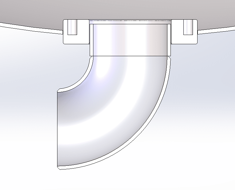
See attached image. My question is concerning the design of the pipe which is to be welded into the ID of the single tap pad flange. I'm thinking that the developed opening should be taken as the ID of the flange. The pipe needs to pass UG-45 calc, and pipe-to-flange welds should be per Fig. UW-16.1, sketch K.

Am I missing anything?

Thank you!

Phil
 
Replies continue below

Recommended for you

You seem to be missing a lot ........

You also seem to have a fillet welded pipe segment as a nozzle for a pressure vessel ... Unless this is very small pipe, I do not believe that this is acceptable to ASME VIII

--- Zero dimensions
--- Weld details for the insert ?
--- Thread/bolting details ?
--- Component names, Code requirements ?

And, most importantly, how big will the person be that has to GET INTO THE VESSEL , to bolt whatever to the inside of the flange (if indeed that is a pad flange)
]

MJCronin
Sr. Process Engineer
 
Yeah, some engineering judgement required here. Perhaps design so that the pipe doesn't contribute towards opening reinforcement. Only the flange.
The fillet weld shear in the pipe weld will be assessed separately.
The notes for sketch w-2 with respect to nozzle loading may be helpful.
 
@DriveMeNuts,
Thank you for the helpful response. My intention is to exclude pipe area in the opening reinforcement calc. I did not see sketch v-1 through w-2 as applicable since the intention is to fillet weld the pipe to the flange on the inside and the outside as in sketch k. Sketch k does not have a G dimension, but it should rightfully be considered. In my design G = 0.08", no external piping loads.

@MJCronin:
I referenced sketch k for the pipe insert weld details. Your other questions reach beyond the scope of my inquiry here. Our typical product uses a double tapped flange. The customization here is the pipe insert, elbow, and WNF (not shown). Please understand that this screenshot was not intended to convey all the details of construction.​

Phil
 
The pad flange is treated just like any of your other pad flanges, and evaluated separately of the pipe.

The pipe is treated just like any other pipe that's welded to an RFSO flange.

inside weld = pipe thickness
outside weld = 1.4 pipe thickness

There's nothing here our of the ordinary. It's definitely an odd setup, but it can easily be replicated by code compliant methods.

UW-16.1(k) should not come into play. Although it would give similar results.
 
This overall geometry is a variation of Sketch v-2 and w-2. You have to think very carefully before deviating from this detail.
What is critical is that the shear thickness of the weld be 1.25xTn, as per the two sketches.
Sketch k says that the sum of weld through thickness t1 + t2 > 1.25xTn.
So adapting the weld dimensions to sketch k for the pipe into the broader Sketch v-2 and w-2 is okay.
 
Be simple: Avoid the pipe. You can weld the elbow directly to the studding flange.
The sketch is (p-2)

Dimensions are not showed by (OP)

Regards
 
Status
Not open for further replies.
Back
Top