Ing. Aponte
Mechanical
Dear Forum Colleagues,
I have some problem in understanding how ASME div. 1 treats welds and efficiency. Little bit of background: I have to design a simple small vessel with design pressure of 0.8 bar but without a dedicated program so I prepared my calculation by hand - following code - and after asked to a friend of mine, who have pvelite, to check my design.
Basis of design:
1)pressure vessel is small and Client think that the expanses for x-ray check will not be covered by the sparing in term of materials using better seams efficiency.
2)for process problems ends has to be flat end
3)temperature is high and close to creep limit but chosen material is outside creep zone. We need to support it with 4 simple legs to avoid transfer to much heat to floor
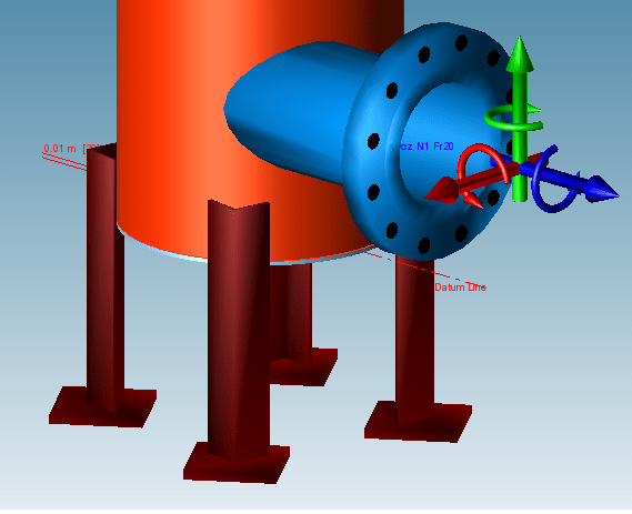
Idea of the project
 .
.
Most of what I don’t understand is included in flat ends pveleite design:
1)pvelite requires on input both longitudinal and circumferential seam efficiency. I agree with my friend that longitudinal doesn’t exist here. He input 1 but for me, because vessel will be built without weld check, should be 0.85 here. Who is right?
2)same problem, on longitudinal seams, on shell: this component will be realized with a seamless pipe 20” diameter. He told me use 1 as longitudinal efficiency but for me it has to be 0.85. Who is right?
3)second point: circumferential seam here is covered by UG-34: I chosen detail g (chamfer on flat head with full penetration from outside). From code C factor is between 0.2 and 0.33. I adopted 0.2 as conservative value, right? In my opinion weld category is corner joint type 7 but code doesn’t indicated a value for efficiency. My friend inserted 0.7: frankly speaking I have not a reason to refuse but if I will proceed like this we will obligated weld all the flat ends by TIG to have a minimal coherency with the selected value. If process is not TIG we have to decrease - maybe 0.6 but I am not sure how much - right?
Last point: where we weld the leg to the equipment we have superimposing of welding. It is correct like this?
Thanks for help and have a nice week end!
I have some problem in understanding how ASME div. 1 treats welds and efficiency. Little bit of background: I have to design a simple small vessel with design pressure of 0.8 bar but without a dedicated program so I prepared my calculation by hand - following code - and after asked to a friend of mine, who have pvelite, to check my design.
Basis of design:
1)pressure vessel is small and Client think that the expanses for x-ray check will not be covered by the sparing in term of materials using better seams efficiency.
2)for process problems ends has to be flat end
3)temperature is high and close to creep limit but chosen material is outside creep zone. We need to support it with 4 simple legs to avoid transfer to much heat to floor
Idea of the project
Most of what I don’t understand is included in flat ends pveleite design:
1)pvelite requires on input both longitudinal and circumferential seam efficiency. I agree with my friend that longitudinal doesn’t exist here. He input 1 but for me, because vessel will be built without weld check, should be 0.85 here. Who is right?
2)same problem, on longitudinal seams, on shell: this component will be realized with a seamless pipe 20” diameter. He told me use 1 as longitudinal efficiency but for me it has to be 0.85. Who is right?
3)second point: circumferential seam here is covered by UG-34: I chosen detail g (chamfer on flat head with full penetration from outside). From code C factor is between 0.2 and 0.33. I adopted 0.2 as conservative value, right? In my opinion weld category is corner joint type 7 but code doesn’t indicated a value for efficiency. My friend inserted 0.7: frankly speaking I have not a reason to refuse but if I will proceed like this we will obligated weld all the flat ends by TIG to have a minimal coherency with the selected value. If process is not TIG we have to decrease - maybe 0.6 but I am not sure how much - right?
Last point: where we weld the leg to the equipment we have superimposing of welding. It is correct like this?
Thanks for help and have a nice week end!
")