Continue to Site

Eng-Tips is the largest engineering community on the Internet

Intelligent Work Forums for Engineering Professionals

  • Congratulations IDS on being selected by the Eng-Tips community for having the most helpful posts in the forums last week. Way to Go!

Auto-Transformer with two line supply- voltage in open phase 3

Status
Not open for further replies.

prc

Electrical
Aug 18, 2001
2,008
Let us consider a case of a 220/132/11kV auto-transformer with and without stabilizing delta tertiary winding. Secondary is not connected to grid. Transformer is 3phase 3 limbed core type with solidly grounded HV neutral.

In case HV primary is fed with rated voltage, but with one line open ( say open breaker contacts)
1) without tertiary:
What will be the voltage on 220 & 132 kV terminals on the phase with open primary line?( due to return flux in third limb)

2) with delta tertiary
(A) same as above
(B) voltage and current distribution in delta tertiary phases.
 
Replies continue below

Recommended for you

I can give a partial answer.
I have wondered also as to the other part of the answer.
We may consider a wye/delta transformer bank for the action due to the delta winding.
The delta winding will cause a back feed to energize the open phase.
With no load the backfed voltage on the open phase will be very close to full voltage.
With a load on the primary circuit, the transformer will present a series impedance of three times the transformer impedance.
The load must be supported by two phases rather than three phases and the line currents and the line voltage drops on the healthy phases will be greater.
The return current will now be passing through the neutral/ground path and the impedance of the ground path will add to the overall voltage drop.
How much voltage drop?
I have to resort to an anecdote;
A number of times I have been in a room when the supply phase was out and we were being supplied by the back feed.
The incandescent lighting level was acceptable.
When our phase was restored there was a small but noticeable increase in the brilliance of the incandescent lights.
In order to analyze this effect, consider a two transformer supply to a three phase load.
This is called an open delta in North America. I don't know what it is called in Europe.
For example consider 100 KVA distribution transformers in open delta.
The virtual transformer formed across the open side of the delta will have the characteristics of a 100 KVA transformer. (Do a vector sketch of the voltage drops under load for illustration. The phase displacement between the two active phases will show the directed sum of the open phase voltage drop to be as I stated.)
Now energize a third 100 KVA transformer across the open side of the delta.
The primary will develop full primary voltage minus voltage drops and will back feed the open phase.
So much for the effect of the delta winding by itself.

Delta winding plus a three legged core.
The phantom delta formed by the three legged core will act as a parallel impedance and the transformer internal voltage drops will be less by an unknown amount.
The line drops will be similar.

Three legged core without a delta winding.
The effect will be similar to a delta winding with an unknown impedance.
Leakage flux may be expected to increase as the load current increases.

The auto-transformer action will be basically the same in all cases, subject to current induced voltage drops.


Bill
--------------------
"Why not the best?"
Jimmy Carter
 
The way I understand the question is that you feed the autotransformer on two HV phases and LV it's unloaded. Is this correct?

For the 1rst case (without tertiary), this is what I come up with:

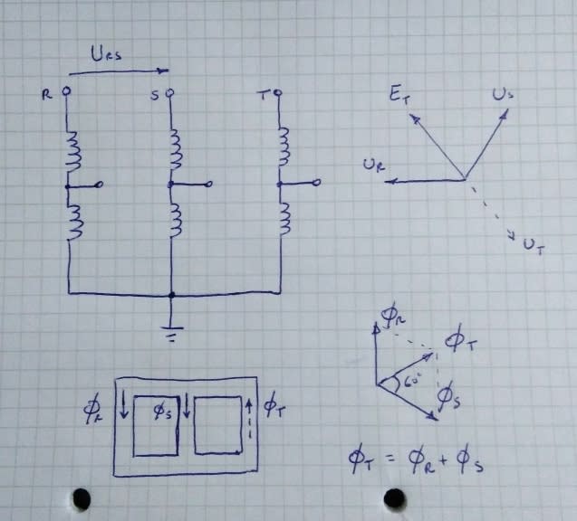
IMG_20200606_130133_pz8ubx.jpg


U representing source voltages and E the induced voltage (emf).

The voltage induced in the open phase (T in my sketch) will be equal in magnitude as the other phases but rotated 180 degrees from what it should be.

I'm still not sure what will be the effect of the presence of a delta tertiary (2nd case). I need to think more about it.
 
IMO with tertiary winding, resultant of emf induced in tertiary winding of two healthy phases will be equal to flux produced by third winding in case of healthy condition. This EMF will lead to appearance of healthy voltage in all windings of transformer.

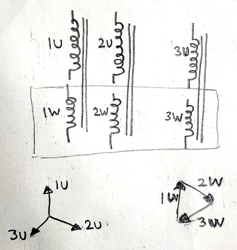
In the image below, say voltage at 3U is missing. Resultant of EMF induced in 1W and 2W would be equal to 3W. This will lead to development to voltage in 3U.

unnamed_1_ialqcq.jpg
 
You are 180 degrees out.
The instantaneous fluxes in each leg sum to zero and the instantaneous voltages in each phase sum to zero.
The three legged core forms a "Phantom Delta".
The delta, real or phantom, replaces the missing phase.
I fought with the wye/delta effect at the distribution level for over 10 years.
At the distribution level, a ground fault anywhere in a circuit may cause primary fuse clearing at wye/delta banks.
At the distribution level, ground fault currents are increased by the back feed contribution of wye/delta transformers or transformer banks.
Search this site.
Wye/delta backfeeds have been discussed a number of times.

Bill
--------------------
"Why not the best?"
Jimmy Carter
 
sushilksk
You are correct.
I was replying to argotier's post.
In the case of a real delta, the effective impedance may be determined from the rated three phase impedance.
In the case of the phantom delta formed by the three legged core, the effective impedance would have to be determined by tests that are not normally conducted.
I have a lot of field experience with wye/delta banks formed by single phase transformer banks.
We did not have any three phase transformers on our small system, so while I am familiar with the general effects of a wye/delta transformer, I can not provide a number for the effective impedance of a phantom delta.
For a real wye/delta, use three times the stated impedance of the transformer for the effective impedance of the back feed circuit.

Bill
--------------------
"Why not the best?"
Jimmy Carter
 
Hello prc,
in all practical cases, if the neutral is grounded, the voltage on the "open" phase will be equal to the expected voltage on that phase, i.e. 1 p.u. with a +120° and -120° shift with respect to the other two phases.
Due to the 3-limbs arrangement, both with and without a delta tertiary, the vectorial sum of the two flux of the connected terminals is equal to the flux on the third (unconnected) terminal.
The same applies for the voltages induced by the aforementioned fluxes.

In practice, both if you have a stuck CB pole or not, you will find the very same voltage to ground on the EHV and HV terminals: it is the same behaviour used during induced voltage tests on YNa 3-limbs units.


Si duri puer ingeni videtur,
preconem facias vel architectum.
 
When I became involved with the little island utility there were two seafood processing plants using wye/delta transformer banks.
Later there was one and finally none.
That took a few years to accomplish.
In the wye/delta days, one wye/delta bank could and would carry the total system load of an open phase.
Due to the extra voltage drops, the voltage on the open phase was a little low, but acceptable.


Bill
--------------------
"Why not the best?"
Jimmy Carter
 
Thank you all for the expert views.

As FPelec stated the voltages were found almost near to rated voltages on low voltage measurements on an actual transformer with tertiary, using 430 V 3 phase supply. A circulating current in tertiary is not possible as there will be no compensating current in other windings.

Appreciate agotier,s analysis.
 
prc; A circulating current in the delta winding is possible and common.
The magnitude of the circulating current is dependent on the load being back-fed on the open phase.
I have lost distribution transformers due to heavy circulating currents as a wye/delta transformer bank tried to correct a low voltage on one phase.
With no load, the transformer on the open phase will be excited by a circulating current in the delta.
That is another aspect of the grounded wye/delta connection.
If one phase voltage is low or high or if there is a phase angle error, the wye/delta bank will try to correct it.
Rural distribution lines with voltage regulators are unfriendly to both wye/delta banks and to induction motors.
Been there, done that, for too many years.


Bill
--------------------
"Why not the best?"
Jimmy Carter
 
A small wye/delta bank will make an effective grounding transformer.
Again, by way of a circulating current in the delta.
By the way, don't be confused by the auto-transformer aspect.
The wye/delta effect is present with or without an auto-transformer tap.

Bill
--------------------
"Why not the best?"
Jimmy Carter
 
Status
Not open for further replies.

Part and Inventory Search

Sponsor