electrical429
Electrical
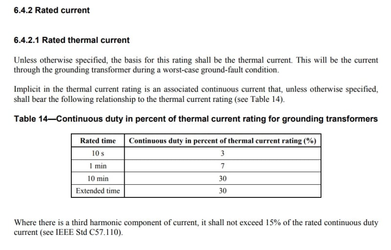
As per IEEE Std C57.32 section 6.4.2 extract below Earthing Transformer continuous rating must be 3% of 10s thermal rated current.

We will be installing ZNyn11 Auxiliary Earthing transformer for the purposes of limiting 132/33 kV YNd11 power transformer 33 kV side earth fault current to 1000 A and providing site LVAC supplies. Aux. ETx will be rated at 1000A for 10s. Site LVAC load is quite small, ~200 kVA. If you go by IEEE Std C57.32 we would require Aux. Tx thermal rating of:
Instr = 1000 A for 10s
Instr per phase = 1000A / 3 = 333 A
Snstr = 3 x 33000 V/sqrt(3) x 333 A = 19.033 MVA
Based on IEEE Std C57.32 continuous rating of transformer should be 3% x 19033 kVA = 517 kVA
What happens if install 200 kVA Aux. Tx rated at 1000 A for 10s? I've seen designs where 200 and 300 kVA Aux. Earthing transformers were rated at 1000A for 10s.
