Continue to Site

Eng-Tips is the largest engineering community on the Internet

Intelligent Work Forums for Engineering Professionals

  • Congratulations KootK on being selected by the Eng-Tips community for having the most helpful posts in the forums last week. Way to Go!

Auxiliary Views in Drawings

Status
Not open for further replies.

dspratt

Mechanical
Mar 26, 2011
4
I've been trying to figure out how to add a view that is parallel to a plane cutting through the corner of a rectangular part.

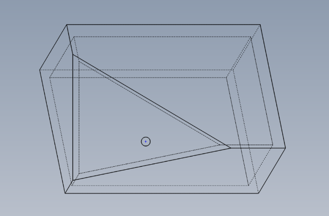
The first image is not what I want. The auxiliary view only shows a view without the third face sticking out, resulting in a view that does not look straight down the hole.

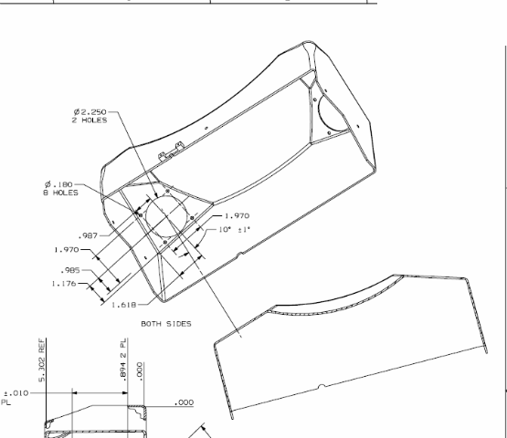
The second image is the one that I want in the drawing.

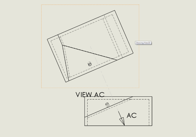
The third image is an example of what I'm looking for.
a7b9b2c1.png


bd54a408.png


a052d9eb.png


Any help would be appreciated.

(Running SolidWorks 2009 through 2011)
 
Replies continue below

Recommended for you

try to use projected (no auxilary) view, then click the face with hole. The arrow add manually as note.
 
When I use projected view, it only lets me do the typical 90 degree offsets and the isometric views. As far as selecting a face is concerned, after clicking the projected view it wants me to select a drawing to work off of and does not let me select a particular face.

Thanks for the suggestion.
 
Correction. I had a hole there. The only option is to put in the model view perpendicular to the surface in part, to add a view Menu->view-> orientation, and inserted into the drawing
 
You need two projection steps to get the view you want.
 
laik: That's what I've done. I don't know if there is a simpler way (or better way, for that matter) to do this.

TheTick: Could you elaborate? I've tried multiple layers of projections but none have given me a view perpendicular to the plane I want.
 
I'm trying to remember how to do this. It's similar to the projections you need to show a compound miter. It involves projecting an auxiliary view from a line normal to the target surface.

I won't be able to try until Monday AM.
 
In the model, create a custom view. Orient the part normal to the face with the hole, hit your space bar and then select new view. You'll then be able to have that view available to drag into your drawing.

Jeff Mirisola, CSWP
Design Manager/Senior Designer
M9 Defense
My Blog
 
JMirisola: This is what I have done. I was curious if there is another way to go about doing it (through aux views or projections). That drawing you see as my example was done in UG. I'm not sure how up to par the drawing toolkit is in SW compared to other utilities.
 
Status
Not open for further replies.

Part and Inventory Search

Sponsor