Eng-Tips is the largest engineering community on the Internet

Intelligent Work Forums for Engineering Professionals

  • Congratulations waross on being selected by the Tek-Tips community for having the most helpful posts in the forums last week. Way to Go!

Average hoope stress at the slope transition from shell to flat cover. 1

Status
Not open for further replies.

mechengineer

Mechanical
Apr 19, 2001
256
0
0
SG
Link
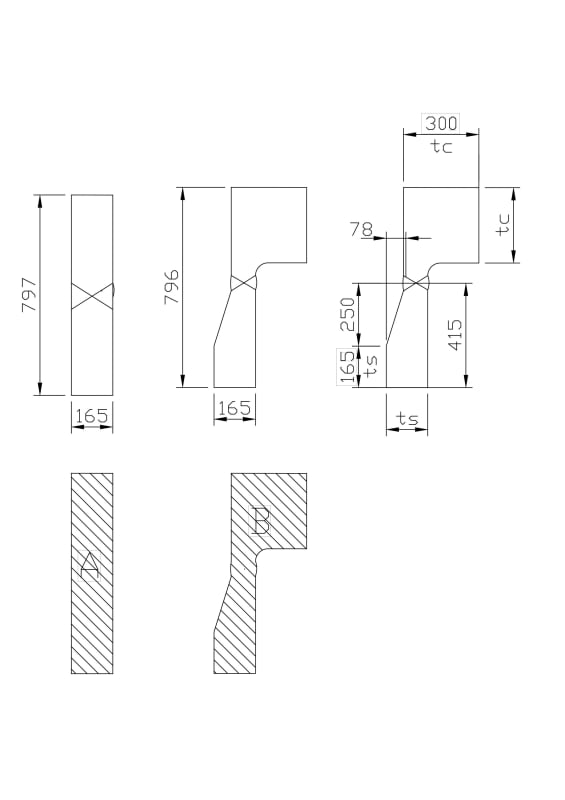
I take the connection of shell to flat cover as an example to show my idea,
a) Considering the reinforcement effect at the transition connection by the thick cover, it requests that area B > area A, so that get the 'average stress' at the slope transition is not larger that the hoope stress in the cylinder wall.
b) the maximum longitudinal stress at the small end of the transition shall not be larger that the longitudinal stress at the cylinder wall (pr/4t).
If the above 'a' and 'b' are satidfied, I think that may allow the thcinkness at the small end of transition being smaller than cylinders shell thickness, but not more than 1/2 of cylinder thickness.
Slope_Connection_ticr7r.jpg
 
Replies continue below

Recommended for you

The method of area replacement is like a thumb rule adopted for Nozzle reinforcement. It is assumed that if you apply that thumb rule the stresses at the nozzle junction are within limits. You should not apply the same thumb rule for Shell to Flat cover junction. The geometry is different here. You need to carry out a detailed evaluation of all the applicable stresses( hoop , meridional , radial , tangential , discontinuity etc ) and then decide if your proposal is acceptable or not.
 
@ Some Curious Guy,
In a simple word, use FEA to analyze the combined stress (second stress + membrane stress). Yes, it is one option I known and seems everything can settle by FEA whatever it is necessary or not, which I do not prefer. But if follow your idea, how do you explain that code does not provide any such stress analysis requirement that you asked for those shell to head connections shown in Figure UW-13.1 and UW-13.2?
Regards,
 
Not necessarily FEA. There are some good reference and procedures given in Appendix 4 of ASME Sec VIII Div 2 2004 edition for evaluating discontinuity stress. Derivation of all code formulas are given in Handbooks from Authors like Bednar , Brownell and Young etc. Please read them and you would get your answers.
As far as I know, code accounts for these extra stresses by considering some extra factors in thickness formulas. Code prescribes certain limits on slope and attachment radius for smooth transition of discontinuity stress. Those assumptions and recommendation given by code must be strictly read in context. Anything read out of context will require you to perform a detailed stress analysis ( not necessarily FEA ).
 
As far as I know and please correct me if I am worng.
When dimensions requirements are provided no additional calculation is required.
 
Yes, correct. See UG-23(c) (2017), second to last and last sentence of first para, concerning discontinuity stresses.

Regards,

Mike

The problem with sloppy work is that the supply FAR EXCEEDS the demand
 
@ Some Curious Guy,
But the case is trapezoidal bending section at shell side, not rectangular.
The slope transition should be lower discontinuity stress as it more 'flexible' constrain. The point is to prove whether the 'average' hoop stress is established. I tend to accept the method of analogy using the 'thumb rule' here.
But if it is not acceptable in practice, I have to use FEA to prove case by case. That will be high cost and I may have to give up.
Regards,
 
The previous link was talking about shell to girth flange, which would not be acceptable for the tapered transition. For the hemi head, the tangent line is at the full cylinder thickness and the transition is part of the head, so material is added from that required by code. Reducing the minimum calculated hoop stress thickness of the cylinder to a girth flange is not acceptable.

From what I can tell there are no dimensioned examples for this configuration. Regarding the stresses at the junction, the discussion depends on whether this is actually a girth flange or a flat end. Regardless, the increase in discontinuity stresses would never justify a thickness reduction.
 
@BJI,
Please provide the evidence and technical analysis to support your option.
My opinions are as following,
1, The transition way of slope at the end of cylinder is only to make a smooth transition to reduce the centerline offset between the thicknesses of spherical head and the cylinder wall to reduce the discontinuity stress. But the slope transition is the true cylinder shape in ID.
2, Code never say that the slope transition portion at the end of cylinder to spherical head shall be considered as spherical head, especially for the determination of the transition wall thickness subjected to membrane stress. The transition is the cylinder shape thus the thickness of the transition shall use the formula of cylinder thickness, but not the formula of spherical head thickness.
3, As for the discontinuity stress here, Design by Rule is only to calculate/analyze pressure parts individually based on primary membrane stress and does not give the discontinued stress analysis at the connection, such as head to shall, flange to shell, flat cover to shell, and cone to shell. It is because that the discontinued stress is localized around the range of 2.5 sqrt(rt) and self-limited for toughness material (YS/TS is around 0.65 for SA516Gr70). And UG-23 (c) states that the discontinuity stress has considered into the allowable stress.
4. Even if it is not from a mechanical point of view, in fabrication view, you would not be able to get the spherical head with such shape of the transition. The transition is made from cylinder shell with a sloped shape in outside. See W.L and T.L of the transition in the attached
Spherical_head_lqnbrx.jpg
 
@Mechengineer
For a cylinder to hemi-head joint
I agree with you that the transition piece is actually a part of cylinder and hence should be treated as a cylinder. What I do not agree is that the thickness of small end of the transition should be calculated from longitudinal stress of cylinder ( t = P d/4 Scyl). Per my understanding the thickness of small end should the thickness from hemihead hoop stress ( th = pd / 4Shead ) . If for example the material of hemisphere has less allowable stress than cylinder then thickness of hemisphere would ofcourse be greater. If instead of hemisphere an ellipsoidal head is attached to the cylinder then thickness of small end should be thickness of elliptical head from hoop stress and not from long stress of cylinder. The transition piece provides a smooth discontinuity and only in some limited region in an around transition a higher allowable stress should be allowed per code ( 2Sy or 3S or 1.5 S whatever it is ). I assume that code might have calculated all this stresses and recommended a value of slope less than 1:3 ( or 1:4 depending on which code you use ) in the transition piece to keep the stress and any deflection between limits.

For cylinder to Flat head joint

I still think you cannot apply the analogy of cylinder to hemi- head transition joint to cylinder to flat cover joint. The geometry is different here. I also have some doubts about the approach of average hoop stress. What I feel is in case of a failure the weakest section would fail first. In this the weakest section would be the small end transition between cylinder and flathead. The thicker section would provide some stiffening effect but how much is that stiffening effect ?. Would this stiffening effect save the smaller and weaker section from failure. Unless there an explicit recommendation given in the code I cannot be sure of the results. Hence I would want a detailed stress and deflection analysis ( FEA is preferred but as I said above other ways and methods are also there )

Hope I have made my position clear. Please also refer to your Authorized Inspector and get his opinion.


@ Some Curious Guy,
In general, I appreciate your thinking in technical analysis. But in my experience, it is hopeless if any calculation issue for stress analysis to ask AI, the answer is confirmed 'Just follow the code!". AI in Singapore mostly concentrate to the inspection and fabrication.
Just out of interest and curiosity, I don't currently have the possibility to put this idea into practice.
Regards,
 
It doesn't matter where the weld is located, and vessels don't require a weld seam, except where necessitated by fabrication considerations. Likewise, the fact that the internal transition is typically straight/parallel to the cylinder ID, doesn't have any relevance to the design or definitions.

You design the hemisphere using PD/4t, which is a half sphere between tangent lines. Then you design the cylinder between tangent lines based on PD/2t. Now you add material to create this transition without reducing the thickness of any part below the code required thickness. This requires adding thickness to the head to form the transition. Logically you place the weld at the small end of the transition, which makes a thick cylindrical section with a taper at the end and a thin section with a spherical profile.

If you refer to UW-13.1 you can see the dotted line of the head extending to the tangent line. The diagram also shows material being added to the thinner of the parts joined. Now refer to UW-13(b)(3) and the extract provided below:

UW-13(b)(3) said:
When the transition is formed by removing material from the thicker section, the minimum thickness of that section, after the material is removed, shall not be less than that required by UG-23(c).

Even though a centreline offset is avoided wherever possible, this type of discontinuity stress is permitted and accepted by the code as stated under UG-23(c). Removing material below the code required thickness is not considered a discontinuity stress. This approach is consistent with fundamental theory and doesn't require any dispensations provided by specific diagrams (if available).

 
@BJI,
Code UG-23 (c) does not provide the method to calculate the discontinuity stress. But the code has considered it into the allowable stress whatever what the type of connection in Figure UW-13.1 & UW-13.2 is.
I just try to use the method of analogy to have some ideas considering and evaluating the discontinuity stress as per the consideration of UG-23 (c).
Regards,
 
A priori of UG-23(c) for discontinuity stresses is that the general primary membrane stress limits are not exceeded. The proposed approach didn't meet this requirement.
 
There is no such thing as a tapered cylinder hoop stress limit. As discussed above, you have a hemispherical head and a cylindrical shell, which need to comply with the general membrane stress limits. Removing material from the cylinder to create the tapered transition violates this requirement, therefore, the transition is added to the head (not a cylinder). Code references were provided above.

The code theory is based the equilibrium model, whereby you can develop free body diagrams for each pressure component, with suitable boundary conditions, and determine the associated stresses and reactions from the applied loads. The allowable stress limits are general membrane and primary bending, consistent with lower bound limit load theory. When you assemble the components, interaction and displacement continuity develops secondary stresses and local membrane stresses. So your discussion of the 'assembled' stress at the small end does not fall under the general membrane limit. This is a simplification and is gets more complicated when you look at splitting primary and secondary stresses in detail, but any part with a general membrane stress limit should still be calculated by hand (free bodies), independent of the adjoining component.

Essentially you need to rethink the tapered cylinder concept, additional reinforcing is added to the thinner part to compensate for discontinuity stresses. For the flange transition proposed, a higher strength pup piece would be required to match the flange small end thickness requirement. Around the flange small end there is additional hoop stress associated with flange bending, so introducing additional discontinuity stresses would not be recommended.
 
Status
Not open for further replies.
Back
Top