Continue to Site

Eng-Tips is the largest engineering community on the Internet

Intelligent Work Forums for Engineering Professionals

  • Congratulations GregLocock on being selected by the Eng-Tips community for having the most helpful posts in the forums last week. Way to Go!

Avoid rainwater drips with dirt on tank shell to decrease repaint rate

Status
Not open for further replies.

danschwind

Mechanical
Sep 12, 2018
191
Dear colleagues,

I am studying an issue for my client and I have stressed my ability to search any existing solution for it.

The issue:
My client owns hundreds (literally) of API 650 vertical storage tanks at various fuel terminals nation-wide (not USA!). As a premise, they are all fixed conical-roof.
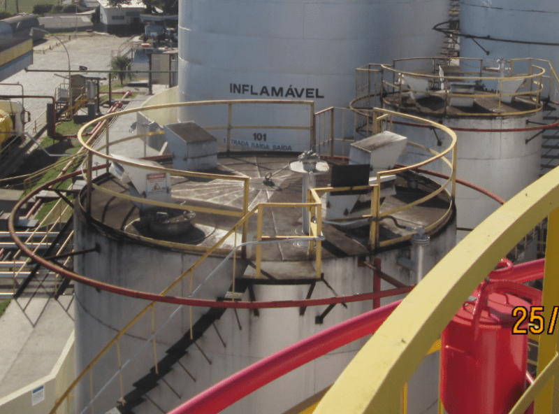
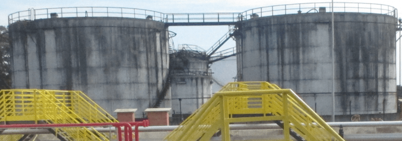
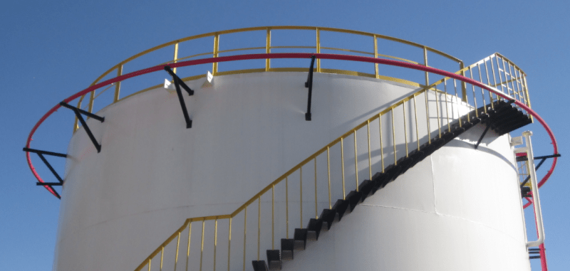
Over time, dirt collects on the tank’s roof and whenever there is rain, this dirt drips on the tank’s shell and the tank’s get visibly dirty. This require constant maintenance by cleaning and increases the rate at which the tanks are repainted.
Capturar_ttliht.png


Capturar4_uaxdue.png


Their wish:
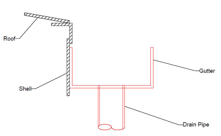
They requested me to find a solution in the form of a barrier for this rainwater to not be able to drip on the tank’s shell. They suggested some sort of gutter that would be installed on the transition of the shell and roof, something like this:
Capturar2_mh1gmz.png


On existing tanks, it would be joined through some sort of cold welding to the shell, to avoid hot work. On future tanks they could be welded normally.

The problems I have identified:
As another premise, all the tanks have a cooling sprinkler ring (sorry if this has a more specific name that I am unaware of) on the top of the shell, as shown in the first picture. The gutter option may interfere with the functioning of those cooling sprinklers.
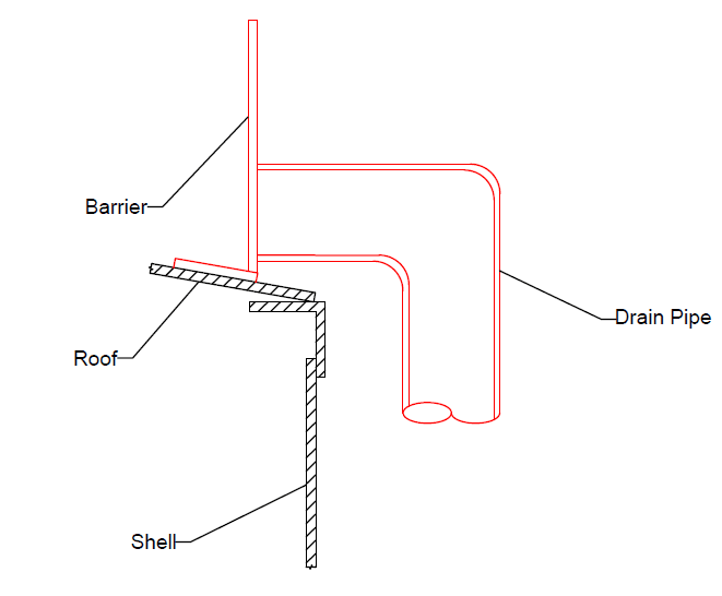
I then thought of something like this, which I named a “barrier”:
Capturar3_yoghrz.png


Which would also be joined through cold welding, albeit now to the roof.

My opinion:
I don’t like either solution. Both would retain some water that would slowly evaporate. The barrier would not be able to be installed right after the exit from the stairs, so it would only partially block the rainwater. The gutter may interfere with the sprinkler ring and would be really painful to install (there are many things extruding out of the tank’s circumference to interfere with the gutter) and would also interfere with the stair.

Tank Data:
Diameter: 5,73m to 19,10m
Height: 7,32m to 17,08m
Thickness of last shell plate: 1/4”
Thickness of roof: 3/16”
Fluids stored: Gasoline, Diesel, Ethanol, Water (fire fighting tank)

Reference for cleanliness:
Capturar1_b6oswe.png


My question:
Any of you guys saw or developed a solution for this? As I’ve said before, I’ve depleted my benchmarking capabilities and kind of come to a conclusion that this is either a “non-issue” for everyone else and therefore no one bothered to sort out or it is something that really has no feasible solution.
I am also not sure whether any of this would comply with API 650. I admit I haven’t read it entirely because, well, it’s huge. But I did an overall search for topics within the standard that would deny any accessory like this one and couldn’t find any.
By the way, I’m not worried about sizing the solution (i.e. the gutter size, the pipe diameter, etc), only the concept is important to me now.
If any of you guys has any thoughts on this, they are most welcomed and I thank you all in advance [smile]
 
Replies continue below

Recommended for you

Can they repaint with something that handles the cleaning process better so that the repaint period is within tolerable limits? I don't know if that's feasible for the company in terms of cost, but I don't readily see a solution that preserves the cooling ring efficacy.
 
Jari, thanks for the answer.

Do you suggest any paint that has an increased resistance to the cleaning process? Painting procedures/paint types are definetely not my forte.

My real wish is to stress all possibilities regarding the feasibility of a system like this before I "give up" and tell them there is really no feasible solution. Then, maybe we can start searching for a revestment able to withstand the cleaning without tearing apart quickly.
 
For new construction, turn the angle out instead of in and it will help.
I'd suggest to look into whether that is actually staining from contaminants or mildew or what, and see if you can get paint formulations that help with either problem.
"Some sort of cold welding" sounds like epoxy glue, and I suspect would be causing as many problems as it solves.
 
Sorry, don't have any paint suggestions to offer. Would you consider finding a way to limit dirt accumulation so the tanks don't get as dirty? I personally think the prevention approach is more fruitful than the remediation approach in this situation. I'd be interested in knowing why the dirt can't be tolerated until it's time to repaint. Is the company concerned with optics? Does the dirt make the tanks retain more heat?

Can you elaborate more on where the water from the cooling ring goes? Does it spray on the roof only? Shell only? Everywhere all at once?
 
One thing to consider here is the potential for inadvertent consequences.

This report below relates to the buncefield incident where the fuel coming out of the vents at the top of the tank spilled fuel and the plates spread the fuel.

The apparent purpose of the plates was to help cooling water sprayed onto the roof to flow down the walls to help cool the walls.

I think also NFPA 11 might have some impact?

Now if you have a gutter arrangement that won't work and might be a significant issue in the design of your firewater cooling ring

Those lower rings you see on the tanks in my experience are stich welded to the roof to allow ater to flow evenly down the walls from the roof.

It looks like you have some pretty dirty roofs!


Remember - More details = better answers
Also: If you get a response it's polite to respond to it.
 
JStephen,thanks for the answer!

This is something that was suggested by my client also. The problem is this may be hard to apply on frangible-roof tanks, as we would have a limit to increase the top angle size. I shall run some calculations to see up to what dimension I can specify the top angle to serve as a sort of "skirt" to the roof.

Jari,

I would consider finding a way to limit dirt accumulation if I knew how to start thinking about this. Do you have any suggestion?
And yes, the reason the tanks are cleaned often is due to aesthetics only. Most of those terminals are very close to busy roads and they have the company's logo on them. This is a practice that I have no power whatsoever to change.

The water from the cooling ring is sprayed on the top portion of the shell and drips down. The cooling ring around the shell is intended to attend only the shell, not the roof. Some tanks also have a dedicated cooling ring on the roof.
My concern is that there is really no standard in the placement of this ring, except that it begins at the top of the shell (some tanks have multiple layers of rings). Although I drew the gutter very close to the roof, in reality it wouldn't be that close. So, some of the water from some of the rings on some of the tanks may be drained by the gutter instead of driping on the shell to cool off the tank. I guess I could add an observation that after installation of a gutter the cooling rings should be tested and in case of improper functioning, their height must be modified to a suitable one.
 
LittleInch, thanks for the answer!

That is actually a pretty good point that I will admit I haven't thought of yet. I will be sure to read the link you shared and will also look at NFPA 11 (even if we are not required to comply with it).
And yes, the roofs are very dirty!

Any thoughts of a deflector plate angled down instead of up (as shown in Figure 7 of your link) and a gutter not face-to-face with the tank, but at a radial distance to "catch" the fluids deflected by the plate?
 
I'm assuming the dirt accumulates from being blown onto the roof of the tank so I was thinking of a curtain type feature (like actual plastic curtain, some sheet metal guards) that would keep wind from blowing across the diameter of the roof. If this is a reasonable approach, that would at least limit the wind egress to the areas where people walk onto the roof from the stairs. Sound remotely plausible?
 
Jari,

Yes, this sound plausible. I will need to mature this idea a little, but it is a very good idea. This material would need to be low-maintenance, low cost (preferrable) and as we are dealing with aesthetics, it should comply with it too.

I will spend my weekend thinking about this. Thank you!

If anyone have any more thoughts in the situation, I'm accepting everything! [smile]
 
You say "... this may be hard to apply on frangible-roof tanks ...". These tanks look very small to be frangible, but I'll assume they are.

Either the gutter or the barrier plate will likely make the roof-to-shell junction non-frangible. They will add to the area and stiffness at the junction, and may prevent the frangible buckling of thejunction from occuring. If this is true then additional venting may be required to handle the API 2000 emergency case.
 
Geoff13, thanks for the answer!

I agree that the gutter may have this effect, but do you reckon the barrier as well? If you consider that a structural member and that Dls = Dlr (thanks, API 650), then it would actually increase the area threshold for it to be considered frangible, no? Although the standard states that all members in the region of the roof-to-shell joint contributes to the cross-sectional area, it doesn't state where is the limit of this region, so it is actually very confusing to me.

But anyway, worst case scenario is that any solution will not be applied to tanks that have frangible-roofs. Will dig more into it.


@LittleInch, the link you shared was very elucidative. If we decide to go with a solution like that I will have the problems caused by that particular solution in mind.
 
The frangible area rule uses the Annex F definitions. The participating roof plate length is thus the smaller of 12" or 0.3 sqrt(R2 th). If all your tanks are as small as the ones in the photos then this distance may only be a couple of inches. I'm used to big tanks where the 12" limit often governs.

You want both the shell and roof to have the opportunity to buckle, so I would leave a wider margin than just the Annex F limit.

Note : The roof plate buckles further in are due to the collapse of some of the roof rafters, not the frangible junction failure.
Junction_mvyfzq.jpg
 
A slight change of topic, but looking back at your "picture for cleanliness" in your original posting.

You've got a sprinkler / cooling ring around the top of the tank, but then it appears that your stair treads, and presumably the intermediate platform, are welded directly to the shell. I would want the stair treads out on a stringer so that there are minimal obstructions to uniform rundown. I would think about whether the area below this stair is suitably protected.
 
Geoff, thanks for the clarification! I consulted the Annex F right now and found this maximum participating roof width that I wasn't aware off. +1 to number of things learnt today :)

If my barrier is within Wh (width of participating roof), I would then need to sum its cross-sectional area (or its portion inside Wh) to the roof-to-shell joint? Same for the gutter and Wc?
 
Geoff,

The stairs are indeed welded to the shell (at least all the stairs of all the tanks I have climbed). I don't think that is really an issue code-wise as there is a provision in our local code that allows us to cool only 1/3 of the tank's shell if there are valves to create sections on the cooling ring.

But, I'm neither a tank-guy or fire-protection-guy, so be skeptic.

 
Annex F shows a number of configirations for the roof-to-shell junction. If you want to come up with something different by adding more pieces you will need to find your own rationale for the participating area after understanding the logic used by API. These figures existed when I started in 1983, so I do not know their history. They appear to be essentially the same as the figures used when Annex F was added in the mid-60's.

I've always understood that 1/3 of the shell is meant to be a way to keep the firewater supply system to a smaller size. With the valves you only need to open the cooling ring zone(s) facing the fire. Not sure that logic extends to the area under the stairs if that's what's facing the fire. I'm also not a firefighting expert, but I will copy clause 7.4.2.5 of NFPA 13 (Standard for Water Spray Fixed Systems for Fire Protection). Clause 7.4 is for "Exposure Protection" systems like yours appears to be.
[ul]
[li]Where projections (manhole flanges, pipe flanges, support brackets, relief valves, etc.) will obstruct water spray coverage, including rundown on vertical surfaces, additional nozzles shall be installed around the projections to maintain the wetting pattern that otherwise would be seriously interrupted.[/li]
[/ul]
 
Thanks Geoff, it was very elucidative.

As for NFPA 13, here we are not required to comply with it. I will check our local codes to see if there is any clause like the one you kindly copied.

I have just returned from a meeting with my client and exposed all the issues that were described here. I also got the information that actually 100% of the tanks have frangible roofs, so I was wrong before.
They reacted well to my pessimism regarding a solution for this particular problem, and we are now trying to figure out some form of hydrophobic or other type of painting that may get less dirty over time.

I thank you all for all the help dispensed in this topic! But if any of you have any other solution, I would gladly want to hear it :)
 
Status
Not open for further replies.

Part and Inventory Search

Sponsor